Hello everyone
QUESTIONs:
What is the broken Part?
Where can I find the replacement part?
Context and background information:
Last year I crashed my P3P into a tree... My gimbal broke into pieces and I had to repair it.
The Drone works again, can fly, has a functional gimbal and can record Videos and take Images to the SD card.
BUT I have no live view (yes I tested different phones/ Ipads/ changed all the wires/ made every possible software up- or downgrade and so on).
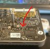
After inspecting the gimbal mainboard, I discovered a little crushed component. During the crash the yaw Arm must have pressed against the mainboard causing the damage (as shown in the images blow).
What I know:
According to this dji forum post Gimbal mainboard damage it is a Quartz resonator which is most probably responsible for the coding of the (low res) 1080p transmission signal.
The Part is described as a "long, plastic covered metal part, 5 or 6 pins; quartz oscillator?" in this very detailed documentation of the gimbal mainboard (o-gs/dji-firmware-tools). I can only see 4 pins but I assume it is the same part.
I measured the length and width of the Part (approx. 7mm by 1.5mm) and found a couple of possible replacement parts but have no clue if the values are correct and which of the parts is the right one. https://mou.sr/2wVa8B9
If you have any advice or more information I would be happy to hear from you.
QUESTIONs:
What is the broken Part?
Where can I find the replacement part?
Context and background information:
Last year I crashed my P3P into a tree... My gimbal broke into pieces and I had to repair it.
The Drone works again, can fly, has a functional gimbal and can record Videos and take Images to the SD card.
BUT I have no live view (yes I tested different phones/ Ipads/ changed all the wires/ made every possible software up- or downgrade and so on).
After inspecting the gimbal mainboard, I discovered a little crushed component. During the crash the yaw Arm must have pressed against the mainboard causing the damage (as shown in the images blow).
What I know:
According to this dji forum post Gimbal mainboard damage it is a Quartz resonator which is most probably responsible for the coding of the (low res) 1080p transmission signal.
The Part is described as a "long, plastic covered metal part, 5 or 6 pins; quartz oscillator?" in this very detailed documentation of the gimbal mainboard (o-gs/dji-firmware-tools). I can only see 4 pins but I assume it is the same part.
I measured the length and width of the Part (approx. 7mm by 1.5mm) and found a couple of possible replacement parts but have no clue if the values are correct and which of the parts is the right one. https://mou.sr/2wVa8B9
If you have any advice or more information I would be happy to hear from you.