Ahh, ok... because I saw the 5.8ghz hardware in the controller. Well, on the power, I'm going by DJI's FCC App for the Phantom. Of course, average power will be much less with the QPSK...but then again, decoding it is where the "gain" in the system is. I didn't test the Phantom like you have (nice!), but I was using my microwave field-strength meter and then thing was pinned out within several feet - which surprised me. It IS running more than I thought. So, what do you think... are they using active phasing of the 4 element "array" in the Phantom? I just cannot imagine that with any SS encoding scheme (capable of 720 video and data) that you can lock up video over 2 miles to a controller with two rubber-duckies on it. These guys are really smart. Why not diode-switch those 4 antennas and actively track the controller? And have you looked at the elements themselves? I have never seen a "scalloped" design like that. Interesting. Anyway, all good fun! And yes, I've shipped over 6000 of the Icom upgrades! I've got a nice shack here! 73's BobHi Bob AB5N,
It's a pleasure to get you on here with P3 funs .. I know your work around ICOM mike for IC 7000 (I have one of that).
I'm curious to know how you measured 750mw (28,75dbm) coming out from P3 bird... I didn't get more than ~20dBm out with a calibrated Agilent Analyzer 8560E, from both P3A and P3P.
The guys at DJI had a nice idea: Use of OFDM with QPSK modulation (quite like DVB-T) to make good video beam coding/decoding through FPGA chip, but they use a terrible spectrum band like 2.4Ghz (jam packed with blutooth/wifi/zigbee, LOS and so on). If it was on 868Mhz band with 100mW the signal goes to moon. It is amazing how big is RF spectrum and how small is the part for free use to people!
As side note 5.8Ghz is used on Inspire 1 RC for inter-RC comunication, it's not used on a P3A/P.


You are using an out of date browser. It may not display this or other websites correctly.
You should upgrade or use an alternative browser.
You should upgrade or use an alternative browser.
Antenna Booster Analysis
- Thread starter RF Guy
- Start date
I see that the controller seems to use 5.8ghz to interlink with another controller for the Inspire 1.What does the P3 use 5.8Ghz for?
You say "other purposes" which got me very curious!
Well, sad to say that we would have to go down in frequency. Truthfully, you'd have to go down to under 100mhz. And there just aren't any un-licensed bands under there. Plus, the antennas would have to be huge! We could go up... but absorption by water doesn't significantly lower until you are at 10GHZ or above. To get maximum range, the Phantom would need to be on a cleaner band- not one filled with home wireless equipment. Luckily, aloft, you are away from home routers. OK, If I wanted to do a distance record, I'd make up a parabolic dish of about 3 feet. You use about a 3 turn corkscrew circular feeder in the center. This would result in a very tight/powerful beam. If you were up at 300 ft and kept line of sight..you could do 20 miles. Problem is, the Phantom can't lift enough battery to do the range! Again, a regular windsurfer design is the best bang for the buck. Next step would be the corkscrew helical design (available now). The range we have now is perfectly balanced - with the payload of battery we can carry. To accomplish what we have now... took a tremendous amount of engineering by DJI. It's a very optimized system. I'm going with a windsurfer design I created and going to practice my flying skills for killer video effects.... BobNice write up. I learned something.
How hard would it be to convert from 2.4 to something that penetrates better, particularly through foliage? Is there a way to take 2.4 signal and change it to something else on both sides? That would be the ultimate Phantom 3 mod.

Yup.... past using the windsurfer upgrade..you are in thinner payback territory. Still, we are pretty obsessive already running these birds around- so going the extra mile for peak performance isn't such a stretch. BobIt doesn't say that surely?
"Conclusion: Because of battery life, making a simple "Beam" antenna by making a reflector - will result in a range boost that is nicely in-line with your maximum travel range. If you go out in a straight line away from your starting point, you'll be able to get a few miles out there and come back with the stock battery safely. Without increasing your battery capacity significantly, there is no reason to boost range over 2-3 miles. "
The point is it's pretty good stock, and going for a more complex (expensive) system such as a beam style antenna with additional elements will give little benefit - because you are already coming close to standard battery range.
It does indeed...but also the angle of the fold in the reflector. Most antennas like this use the hard-crease..V-shaped reflector - less than 90 degrees. There isn't room for this with the controller antennas though.So to design a corner reflector, how far behind the stock whip antenna would the corner be? I'm guessing it probably has to do with the wavelength?
I can tell you from experience that the distance for the antenna to reflector for 2.4ghz is normally about 2 inches. Vary the reflector angle... and that "focal point" changes. Here is an article on designing them...from 1940. Oh, and the reflector Always extends past the length of the antenna.
To use this article, you have to know that wavelength in meters = 300/ frequency in mhz (2400 in our case) I'll make and give details for a perfected windsurfer-type antenna soon.
http://www.arrl.org/files/file/History/History of QST Volume 1 - Technology/QS11-40-Kraus.pdf
Last edited:
- Joined
- Apr 20, 2014
- Messages
- 210
- Reaction score
- 8

N017RW
Premium Pilot
- Joined
- Apr 20, 2014
- Messages
- 210
- Reaction score
- 8
Only used one corner reflector and got >2k' with full antenna. This was while the P3A was in visible sight (albeit barely visible).
This is FAR greater than I got with the P3S. I'm sure it's a combination of reasons.
Does the P3A and P3P send and receive controls/AV via the same antenna?
Edit, I did notice reception is terrible when directly above.
This is FAR greater than I got with the P3S. I'm sure it's a combination of reasons.
Does the P3A and P3P send and receive controls/AV via the same antenna?
Edit, I did notice reception is terrible when directly above.
Attachments
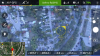
Does that show you at an altitude of 1000ft?Only used one corner reflector and got >2k' with full antenna. This was while the P3A was in visible sight (albeit barely visible).
This is FAR greater than I got with the P3S. I'm sure it's a combination of reasons.
Does the P3A and P3P send and receive controls/AV via the same antenna?
Edit, I did notice reception is terrible when directly above.
- Joined
- Sep 20, 2015
- Messages
- 281
- Reaction score
- 86
- Age
- 28
Only used one corner reflector and got >2k' with full antenna. This was while the P3A was in visible sight (albeit barely visible).
This is FAR greater than I got with the P3S. I'm sure it's a combination of reasons.
Does the P3A and P3P send and receive controls/AV via the same antenna?
Edit, I did notice reception is terrible when directly above.
1000 feet?
This is why drones need registration. Or DJI to restrict their altitude to 400 in the controller.
- Joined
- Apr 20, 2014
- Messages
- 210
- Reaction score
- 8
1000 feet?
This is why drones need registration. Or DJI to restrict their altitude to 400 in the controller.
I've been flying for over 20 years and haven't done anything illegal. You on the otherhand should keep it under 100'
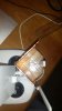
Well I made one prototype. Looking for comment.
90 deg corner reflector. 4.5" tall x 2" x 2". The corner is 2" behind the center of the whip antenna. Used copper tape.
Nice! the reflector needs to come out more though...quite a bit past the antenna. (optimally)
Perfect.
My pleasure! More to come... I'm mod-crazy when it comes to tweaking RF performance.Thank Bob. Much better understanding. Thanks for taking the time.

- Joined
- Nov 1, 2015
- Messages
- 117
- Reaction score
- 40
- Age
- 65
When you design a practical version.. why don'tMy pleasure! More to come... I'm mod-crazy when it comes to tweaking RF performance.
you market it to us
") I just watched a YouTube where a guy puts blank CD's right up against his antennae and is selling that rig for 20 bucks... based on your writings here, that's CRAPPola... if you made something.. and sold/marketed it... I'm IN
I just watched a YouTube where a guy puts blank CD's right up against his antennae and is selling that rig for 20 bucks... based on your writings here, that's CRAPPola... if you made something.. and sold/marketed it... I'm IN OMG!!!Hey guys- ( pre-apologize for the length of this- but it might be useful)
I'm a new P3P owner and it's a rainy day. I'm also an RF engineer. I've spent 4 decades optimizing
signals / antennas / transmitters / receivers. The Windsurfer style antenna boosters were a great idea for the Phantom series. Thing is, I can tell from it's design that nobody has really put the calculator to optimizing it. I'm going to do so. We can do a full analysis of the antenna's "gain" and "pattern". It's likely that the various basic designs of the ones out there are within 20% of a perfect design. They are close - but not optimum. I'll offer easy to understand theory here too- so folks can grasp exactly what is going on - and use these reflectors to the best advantage.
Part 1: The current reflector design is whats called a "Corner Reflector" or "Parabolic Reflector" antenna. The added part is the reflector. As you might imagine, it reflects the radiated RF from the controllers antenna - towards a forward direction instead of 360. Antenna designs don't amplify the signal, they concentrate it. And they don't just take the rear 180 degrees of radiated power - and face it forward. It's more complex than that.
Antennas are rated in "DBi gain". This DBi gain is compared to an imaginary pin-head antenna that has a perfectly even radiation pattern - like a 360 degree sphere. No antenna does this... ALL antennas have a "pattern" that is not equal in all directions. You design them to make the pattern you desire. The more you concentrate the power in one direction, the narrower the signal's "Beamwidth" becomes...like focusing a flashlight or hose. You don't get something for nothing! The signal is reduced to the rear. This is called the "Front to back ratio" - and is also in DB. Most times, you Want a lower signal to the rear. In our case, not so much.
Part 2: Because antennas are fed with RF energy of a certain frequency, the conducting elements of the antenna have to be "resonant". They have to be the correct length so that the RF wave reaches it's end - at the end of the antenna. If the antenna is not the right length, some of the power will be bounced back towards the transmitter and cause heat build-up. This is what's called SWR.. or Standing Wave Ratio. It need's to be 1 to 1.. or 1:1.Designers optimize an antenna's design for "resonance" and signal "pattern" (as well as it's beamwidth)
Part 3: In designing antennas, usually only one piece of metal is actually fed with the power from the transmitter. The rest of the antenna interacts with that "hot" element through the air (called "passive" elements). The spacing and size of all the other elements of the antenna have to be exact - to operate optimally. Changing these sizes will change the antenna's "pattern" of radiation. In the case of a corner reflector, the distance from the real antenna element and the reflector is critical. The size of the reflector is also critical. Usually, designers use a reflector with a fold /crease in it (like a "V") - rather than the parabolic reflector (smooth curve) like the windsurfer design. Corner reflector antennas like this can give 12-15DB of forward gain. That's about 13-17 times concentration of the power forward! They reduce the signal to the rear of the reflector by 25DB...That means that less than 1/100th of the original signal is going backwards. Up close, you can get to the Phantom if it was in back of your reflector antenna, but out at any range, if you faced away from it, it Would loose your signal using a "beam" antenna like this.
Part 4: 2.4 gigahertz is the band used by the Phantom (it uses 5.8ghz for other purposes). It is a microwave band just above microwave oven operating frequency (2.2ghz). It's known to engineers as "S" band. It is a "Line-of-Sight" frequency. Since it is so close to microwave oven operating frequencies, it too will be absorbed by water easily. Trees, leaves, dirt, rain...all convert 2.4 ghz into heat. Thus, your range will be near zero if you are blocked by any significant water-bearing thing. Wet bricks absorb 2.4ghz nicely. Conversely, if YOU are elevated to a good vantage point - above average elevation - and have a clear view of your Phantom over existing terrain, you can have phenomenal range. If you have normal trees and are at ground level, you'll have to increase the Phantom's elevation as you go away- to maintain line-of-sign signal conditions. The Phantom 3 uses a 4 element "Phased Array" with it's antenna elements in the legs. If you put a larger parabolic dish (like 24") on the Phantom controller, you could probably cover a range of 10 miles line of sight.
Part 5: Short... Antennas have polarity. They favor horizontal or vertical usually. If the transmit antenna is "cross-pole" or 90 degrees off from the receiving end, at least half the power is lost. The Phantom's antennas are Vertical. Your controller antennas should be too. Here is the catch: The craft rotates in relation to you. It's overhead, then it is in front...it's signal is bouncing all over the place and rotates in space before it gets to you. This was first seen in Spacecraft as satellites rotated and the ground stations had signal fading. The Russians invented the Helix- or circular antenna for this. It is the corkscrew design you see on one of the aftermarket antenna upgrades- AND the new Drone jammers. A helix transmits equally in both planes...half as much power in each though. A short one does not have much gain. FM stations use circular polarization in order to get to moving cars. Once you make the corkscrew longer, you get gain.. and narrower beamwidth.
(Like over 6 inches on 2.4 ghz)
Conclusion: Because of battery life, making a simple "Beam" antenna by making a reflector - will result in a range boost that is nicely in-line with your maximum travel range. If you go out in a straight line away from your starting point, you'll be able to get a few miles out there and come back with the stock battery safely. Without increasing your battery capacity significantly, there is no reason to boost range over 2-3 miles. Operating your Phantom past where you can see is is actually against FAA rules anyhow - and puts you at much greater risk of loosing your bird. The Controller is transmitting at 38 milliwatts -not much. But the Phantom is transmitting with around 750 milliwatts and the 4 elements in it's legs provide "gain". It wouldn't matter which side you improved the gain of the antenna on- the communications link between them would improve. The gain of the antennas helps the receiving side equally. Engineers sit there and run all the numbers (antenna gain, TX power, receive sensitivity, computer signal decoding gain, frequency path loss) to figure out weather the system is going to work- and over what distance. And Height is much more important than power and antennas. Get your controller up and in the clear- and you are in control!
Lastly: The Phantom's engineers have done a fantastic job in this RF system. Think of a router and how far WiFi goes on the same 2.4ghz band. The Phantom uses Spread Spectrum transmission techniques in which the computer decoding the signal can add gain - buy using what is called FFT - of Fast Fourier Transform. It is able to discriminate desired information from background noise by knowing what "should" be real information - mathematically. In other digital signalling systems, it allows decoding of very weak signals which are actually below the background hiss of the earth. Your GPS does this. All said, the Phantom system is highly optimized and certainly to be admired as a piece of engineering. Bob - AB5N
+1
Similar threads
- Replies
- 11
- Views
- 13K
- Replies
- 3
- Views
- 530
- Replies
- 3
- Views
- 649
- Replies
- 6
- Views
- 2K


Recent Posts
-
 North Jersey, Very new old guy trying to get off the ground with a P330Z Phantom 2
- Latest: captainmilehigh
-

-

-

-
