I''l agree with Marknmd. I would say if the water is like a mirror ( no waves) you would get the waves to bounce off and as Marknmd said "Experience will answer the question" I had flown over the same field with great signal strength out to 12 or 13k and other days I was maybe 3 or 4 k. The only thing that chanced was the highest of the field as in alfalfa field. If the Alfalfa was tall I would get weak signal (absorbing the signal) on days that the alfalfa was cut short, great signal. I was flying about 100 feet high.


You are using an out of date browser. It may not display this or other websites correctly.
You should upgrade or use an alternative browser.
You should upgrade or use an alternative browser.
Antenna Booster Analysis
- Thread starter RF Guy
- Start date

- Joined
- Mar 5, 2014
- Messages
- 4
- Reaction score
- 0
Hey guys- ( pre-apologize for the length of this- but it might be useful)
I'm a new P3P owner and it's a rainy day. I'm also an RF engineer. I've spent 4 decades optimizing
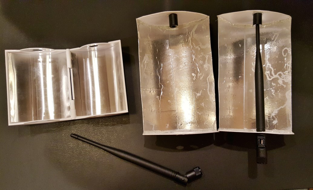
signals / antennas / transmitters / receivers. The Windsurfer style antenna boosters were a great idea for the Phantom series. Thing is, I can tell from it's design that nobody has really put the calculator to optimizing it. I'm going to do so. We can do a full analysis of the antenna's "gain" and "pattern". It's likely that the various basic designs of the ones out there are within 20% of a perfect design. They are close - but not optimum. I'll offer easy to understand theory here too- so folks can grasp exactly what is going on - and use these reflectors to the best advantage.
Part 1: The current reflector design is whats called a "Corner Reflector" or "Parabolic Reflector" antenna. The added part is the reflector. As you might imagine, it reflects the radiated RF from the controllers antenna - towards a forward direction instead of 360. Antenna designs don't amplify the signal, they concentrate it. And they don't just take the rear 180 degrees of radiated power - and face it forward. It's more complex than that.
Antennas are rated in "DBi gain". This DBi gain is compared to an imaginary pin-head antenna that has a perfectly even radiation pattern - like a 360 degree sphere. No antenna does this... ALL antennas have a "pattern" that is not equal in all directions. You design them to make the pattern you desire. The more you concentrate the power in one direction, the narrower the signal's "Beamwidth" becomes...like focusing a flashlight or hose. You don't get something for nothing! The signal is reduced to the rear. This is called the "Front to back ratio" - and is also in DB. Most times, you Want a lower signal to the rear. In our case, not so much.
Part 2: Because antennas are fed with RF energy of a certain frequency, the conducting elements of the antenna have to be "resonant". They have to be the correct length so that the RF wave reaches it's end - at the end of the antenna. If the antenna is not the right length, some of the power will be bounced back towards the transmitter and cause heat build-up. This is what's called SWR.. or Standing Wave Ratio. It need's to be 1 to 1.. or 1:1.Designers optimize an antenna's design for "resonance" and signal "pattern" (as well as it's beamwidth)
Part 3: In designing antennas, usually only one piece of metal is actually fed with the power from the transmitter. The rest of the antenna interacts with that "hot" element through the air (called "passive" elements). The spacing and size of all the other elements of the antenna have to be exact - to operate optimally. Changing these sizes will change the antenna's "pattern" of radiation. In the case of a corner reflector, the distance from the real antenna element and the reflector is critical. The size of the reflector is also critical. Usually, designers use a reflector with a fold /crease in it (like a "V") - rather than the parabolic reflector (smooth curve) like the windsurfer design. Corner reflector antennas like this can give 12-15DB of forward gain. That's about 13-17 times concentration of the power forward! They reduce the signal to the rear of the reflector by 25DB...That means that less than 1/100th of the original signal is going backwards. Up close, you can get to the Phantom if it was in back of your reflector antenna, but out at any range, if you faced away from it, it Would loose your signal using a "beam" antenna like this.
Part 4: 2.4 gigahertz is the band used by the Phantom (it uses 5.8ghz for other purposes). It is a microwave band just above microwave oven operating frequency (2.2ghz). It's known to engineers as "S" band. It is a "Line-of-Sight" frequency. Since it is so close to microwave oven operating frequencies, it too will be absorbed by water easily. Trees, leaves, dirt, rain...all convert 2.4 ghz into heat. Thus, your range will be near zero if you are blocked by any significant water-bearing thing. Wet bricks absorb 2.4ghz nicely. Conversely, if YOU are elevated to a good vantage point - above average elevation - and have a clear view of your Phantom over existing terrain, you can have phenomenal range. If you have normal trees and are at ground level, you'll have to increase the Phantom's elevation as you go away- to maintain line-of-sign signal conditions. The Phantom 3 uses a 4 element "Phased Array" with it's antenna elements in the legs. If you put a larger parabolic dish (like 24") on the Phantom controller, you could probably cover a range of 10 miles line of sight.
Part 5: Short... Antennas have polarity. They favor horizontal or vertical usually. If the transmit antenna is "cross-pole" or 90 degrees off from the receiving end, at least half the power is lost. The Phantom's antennas are Vertical. Your controller antennas should be too. Here is the catch: The craft rotates in relation to you. It's overhead, then it is in front...it's signal is bouncing all over the place and rotates in space before it gets to you. This was first seen in Spacecraft as satellites rotated and the ground stations had signal fading. The Russians invented the Helix- or circular antenna for this. It is the corkscrew design you see on one of the aftermarket antenna upgrades- AND the new Drone jammers. A helix transmits equally in both planes...half as much power in each though. A short one does not have much gain. FM stations use circular polarization in order to get to moving cars. Once you make the corkscrew longer, you get gain.. and narrower beamwidth.
(Like over 6 inches on 2.4 ghz)
Conclusion: Because of battery life, making a simple "Beam" antenna by making a reflector - will result in a range boost that is nicely in-line with your maximum travel range. If you go out in a straight line away from your starting point, you'll be able to get a few miles out there and come back with the stock battery safely. Without increasing your battery capacity significantly, there is no reason to boost range over 2-3 miles. Operating your Phantom past where you can see is is actually against FAA rules anyhow - and puts you at much greater risk of loosing your bird. The Controller is transmitting at 38 milliwatts -not much. But the Phantom is transmitting with around 750 milliwatts and the 4 elements in it's legs provide "gain". It wouldn't matter which side you improved the gain of the antenna on- the communications link between them would improve. The gain of the antennas helps the receiving side equally. Engineers sit there and run all the numbers (antenna gain, TX power, receive sensitivity, computer signal decoding gain, frequency path loss) to figure out weather the system is going to work- and over what distance. And Height is much more important than power and antennas. Get your controller up and in the clear- and you are in control!
Lastly: The Phantom's engineers have done a fantastic job in this RF system. Think of a router and how far WiFi goes on the same 2.4ghz band. The Phantom uses Spread Spectrum transmission techniques in which the computer decoding the signal can add gain - buy using what is called FFT - of Fast Fourier Transform. It is able to discriminate desired information from background noise by knowing what "should" be real information - mathematically. In other digital signalling systems, it allows decoding of very weak signals which are actually below the background hiss of the earth. Your GPS does this. All said, the Phantom system is highly optimized and certainly to be admired as a piece of engineering. Bob - AB5N
Hey guys- ( pre-apologize for the length of this- but it might be useful)
I'm a new P3P owner and it's a rainy day. I'm also an RF engineer. I've spent 4 decades optimizing
signals / antennas / transmitters / receivers. The Windsurfer style antenna boosters were a great idea for the Phantom series. Thing is, I can tell from it's design that nobody has really put the calculator to optimizing it. I'm going to do so. We can do a full analysis of the antenna's "gain" and "pattern". It's likely that the various basic designs of the ones out there are within 20% of a perfect design. They are close - but not optimum. I'll offer easy to understand theory here too- so folks can grasp exactly what is going on - and use these reflectors to the best advantage.
Part 1: The current reflector design is whats called a "Corner Reflector" or "Parabolic Reflector" antenna. The added part is the reflector. As you might imagine, it reflects the radiated RF from the controllers antenna - towards a forward direction instead of 360. Antenna designs don't amplify the signal, they concentrate it. And they don't just take the rear 180 degrees of radiated power - and face it forward. It's more complex than that.
Antennas are rated in "DBi gain". This DBi gain is compared to an imaginary pin-head antenna that has a perfectly even radiation pattern - like a 360 degree sphere. No antenna does this... ALL antennas have a "pattern" that is not equal in all directions. You design them to make the pattern you desire. The more you concentrate the power in one direction, the narrower the signal's "Beamwidth" becomes...like focusing a flashlight or hose. You don't get something for nothing! The signal is reduced to the rear. This is called the "Front to back ratio" - and is also in DB. Most times, you Want a lower signal to the rear. In our case, not so much.
Part 2: Because antennas are fed with RF energy of a certain frequency, the conducting elements of the antenna have to be "resonant". They have to be the correct length so that the RF wave reaches it's end - at the end of the antenna. If the antenna is not the right length, some of the power will be bounced back towards the transmitter and cause heat build-up. This is what's called SWR.. or Standing Wave Ratio. It need's to be 1 to 1.. or 1:1.Designers optimize an antenna's design for "resonance" and signal "pattern" (as well as it's beamwidth)
Part 3: In designing antennas, usually only one piece of metal is actually fed with the power from the transmitter. The rest of the antenna interacts with that "hot" element through the air (called "passive" elements). The spacing and size of all the other elements of the antenna have to be exact - to operate optimally. Changing these sizes will change the antenna's "pattern" of radiation. In the case of a corner reflector, the distance from the real antenna element and the reflector is critical. The size of the reflector is also critical. Usually, designers use a reflector with a fold /crease in it (like a "V") - rather than the parabolic reflector (smooth curve) like the windsurfer design. Corner reflector antennas like this can give 12-15DB of forward gain. That's about 13-17 times concentration of the power forward! They reduce the signal to the rear of the reflector by 25DB...That means that less than 1/100th of the original signal is going backwards. Up close, you can get to the Phantom if it was in back of your reflector antenna, but out at any range, if you faced away from it, it Would loose your signal using a "beam" antenna like this.
Part 4: 2.4 gigahertz is the band used by the Phantom (it uses 5.8ghz for other purposes). It is a microwave band just above microwave oven operating frequency (2.2ghz). It's known to engineers as "S" band. It is a "Line-of-Sight" frequency. Since it is so close to microwave oven operating frequencies, it too will be absorbed by water easily. Trees, leaves, dirt, rain...all convert 2.4 ghz into heat. Thus, your range will be near zero if you are blocked by any significant water-bearing thing. Wet bricks absorb 2.4ghz nicely. Conversely, if YOU are elevated to a good vantage point - above average elevation - and have a clear view of your Phantom over existing terrain, you can have phenomenal range. If you have normal trees and are at ground level, you'll have to increase the Phantom's elevation as you go away- to maintain line-of-sign signal conditions. The Phantom 3 uses a 4 element "Phased Array" with it's antenna elements in the legs. If you put a larger parabolic dish (like 24") on the Phantom controller, you could probably cover a range of 10 miles line of sight.
Part 5: Short... Antennas have polarity. They favor horizontal or vertical usually. If the transmit antenna is "cross-pole" or 90 degrees off from the receiving end, at least half the power is lost. The Phantom's antennas are Vertical. Your controller antennas should be too. Here is the catch: The craft rotates in relation to you. It's overhead, then it is in front...it's signal is bouncing all over the place and rotates in space before it gets to you. This was first seen in Spacecraft as satellites rotated and the ground stations had signal fading. The Russians invented the Helix- or circular antenna for this. It is the corkscrew design you see on one of the aftermarket antenna upgrades- AND the new Drone jammers. A helix transmits equally in both planes...half as much power in each though. A short one does not have much gain. FM stations use circular polarization in order to get to moving cars. Once you make the corkscrew longer, you get gain.. and narrower beamwidth.
(Like over 6 inches on 2.4 ghz)
Conclusion: Because of battery life, making a simple "Beam" antenna by making a reflector - will result in a range boost that is nicely in-line with your maximum travel range. If you go out in a straight line away from your starting point, you'll be able to get a few miles out there and come back with the stock battery safely. Without increasing your battery capacity significantly, there is no reason to boost range over 2-3 miles. Operating your Phantom past where you can see is is actually against FAA rules anyhow - and puts you at much greater risk of loosing your bird. The Controller is transmitting at 38 milliwatts -not much. But the Phantom is transmitting with around 750 milliwatts and the 4 elements in it's legs provide "gain". It wouldn't matter which side you improved the gain of the antenna on- the communications link between them would improve. The gain of the antennas helps the receiving side equally. Engineers sit there and run all the numbers (antenna gain, TX power, receive sensitivity, computer signal decoding gain, frequency path loss) to figure out weather the system is going to work- and over what distance. And Height is much more important than power and antennas. Get your controller up and in the clear- and you are in control!
Lastly: The Phantom's engineers have done a fantastic job in this RF system. Think of a router and how far WiFi goes on the same 2.4ghz band. The Phantom uses Spread Spectrum transmission techniques in which the computer decoding the signal can add gain - buy using what is called FFT - of Fast Fourier Transform. It is able to discriminate desired information from background noise by knowing what "should" be real information - mathematically. In other digital signalling systems, it allows decoding of very weak signals which are actually below the background hiss of the earth. Your GPS does this. All said, the Phantom system is highly optimized and certainly to be admired as a piece of engineering. Bob - AB5N
- Joined
- Mar 5, 2014
- Messages
- 4
- Reaction score
- 0
Just a little south of you in Bosser City. I would like to go in another way. I have a way of elevating my antenna by way of a extendable portable fiberglass pole used by electrical companies to about 30 feet AGL with a patch antenna on top. My question is the will the 40 foot of coax be a problem. Thanks SGHey guys- ( pre-apologize for the length of this- but it might be useful)
I'm a new P3P owner and it's a rainy day. I'm also an RF engineer. I've spent 4 decades optimizing
signals / antennas / transmitters / receivers. The Windsurfer style antenna boosters were a great idea for the Phantom series. Thing is, I can tell from it's design that nobody has really put the calculator to optimizing it. I'm going to do so. We can do a full analysis of the antenna's "gain" and "pattern". It's likely that the various basic designs of the ones out there are within 20% of a perfect design. They are close - but not optimum. I'll offer easy to understand theory here too- so folks can grasp exactly what is going on - and use these reflectors to the best advantage.
Part 1: The current reflector design is whats called a "Corner Reflector" or "Parabolic Reflector" antenna. The added part is the reflector. As you might imagine, it reflects the radiated RF from the controllers antenna - towards a forward direction instead of 360. Antenna designs don't amplify the signal, they concentrate it. And they don't just take the rear 180 degrees of radiated power - and face it forward. It's more complex than that.
Antennas are rated in "DBi gain". This DBi gain is compared to an imaginary pin-head antenna that has a perfectly even radiation pattern - like a 360 degree sphere. No antenna does this... ALL antennas have a "pattern" that is not equal in all directions. You design them to make the pattern you desire. The more you concentrate the power in one direction, the narrower the signal's "Beamwidth" becomes...like focusing a flashlight or hose. You don't get something for nothing! The signal is reduced to the rear. This is called the "Front to back ratio" - and is also in DB. Most times, you Want a lower signal to the rear. In our case, not so much.
Part 2: Because antennas are fed with RF energy of a certain frequency, the conducting elements of the antenna have to be "resonant". They have to be the correct length so that the RF wave reaches it's end - at the end of the antenna. If the antenna is not the right length, some of the power will be bounced back towards the transmitter and cause heat build-up. This is what's called SWR.. or Standing Wave Ratio. It need's to be 1 to 1.. or 1:1.Designers optimize an antenna's design for "resonance" and signal "pattern" (as well as it's beamwidth)
Part 3: In designing antennas, usually only one piece of metal is actually fed with the power from the transmitter. The rest of the antenna interacts with that "hot" element through the air (called "passive" elements). The spacing and size of all the other elements of the antenna have to be exact - to operate optimally. Changing these sizes will change the antenna's "pattern" of radiation. In the case of a corner reflector, the distance from the real antenna element and the reflector is critical. The size of the reflector is also critical. Usually, designers use a reflector with a fold /crease in it (like a "V") - rather than the parabolic reflector (smooth curve) like the windsurfer design. Corner reflector antennas like this can give 12-15DB of forward gain. That's about 13-17 times concentration of the power forward! They reduce the signal to the rear of the reflector by 25DB...That means that less than 1/100th of the original signal is going backwards. Up close, you can get to the Phantom if it was in back of your reflector antenna, but out at any range, if you faced away from it, it Would loose your signal using a "beam" antenna like this.
Part 4: 2.4 gigahertz is the band used by the Phantom (it uses 5.8ghz for other purposes). It is a microwave band just above microwave oven operating frequency (2.2ghz). It's known to engineers as "S" band. It is a "Line-of-Sight" frequency. Since it is so close to microwave oven operating frequencies, it too will be absorbed by water easily. Trees, leaves, dirt, rain...all convert 2.4 ghz into heat. Thus, your range will be near zero if you are blocked by any significant water-bearing thing. Wet bricks absorb 2.4ghz nicely. Conversely, if YOU are elevated to a good vantage point - above average elevation - and have a clear view of your Phantom over existing terrain, you can have phenomenal range. If you have normal trees and are at ground level, you'll have to increase the Phantom's elevation as you go away- to maintain line-of-sign signal conditions. The Phantom 3 uses a 4 element "Phased Array" with it's antenna elements in the legs. If you put a larger parabolic dish (like 24") on the Phantom controller, you could probably cover a range of 10 miles line of sight.
Part 5: Short... Antennas have polarity. They favor horizontal or vertical usually. If the transmit antenna is "cross-pole" or 90 degrees off from the receiving end, at least half the power is lost. The Phantom's antennas are Vertical. Your controller antennas should be too. Here is the catch: The craft rotates in relation to you. It's overhead, then it is in front...it's signal is bouncing all over the place and rotates in space before it gets to you. This was first seen in Spacecraft as satellites rotated and the ground stations had signal fading. The Russians invented the Helix- or circular antenna for this. It is the corkscrew design you see on one of the aftermarket antenna upgrades- AND the new Drone jammers. A helix transmits equally in both planes...half as much power in each though. A short one does not have much gain. FM stations use circular polarization in order to get to moving cars. Once you make the corkscrew longer, you get gain.. and narrower beamwidth.
(Like over 6 inches on 2.4 ghz)
Conclusion: Because of battery life, making a simple "Beam" antenna by making a reflector - will result in a range boost that is nicely in-line with your maximum travel range. If you go out in a straight line away from your starting point, you'll be able to get a few miles out there and come back with the stock battery safely. Without increasing your battery capacity significantly, there is no reason to boost range over 2-3 miles. Operating your Phantom past where you can see is is actually against FAA rules anyhow - and puts you at much greater risk of loosing your bird. The Controller is transmitting at 38 milliwatts -not much. But the Phantom is transmitting with around 750 milliwatts and the 4 elements in it's legs provide "gain". It wouldn't matter which side you improved the gain of the antenna on- the communications link between them would improve. The gain of the antennas helps the receiving side equally. Engineers sit there and run all the numbers (antenna gain, TX power, receive sensitivity, computer signal decoding gain, frequency path loss) to figure out weather the system is going to work- and over what distance. And Height is much more important than power and antennas. Get your controller up and in the clear- and you are in control!
Lastly: The Phantom's engineers have done a fantastic job in this RF system. Think of a router and how far WiFi goes on the same 2.4ghz band. The Phantom uses Spread Spectrum transmission techniques in which the computer decoding the signal can add gain - buy using what is called FFT - of Fast Fourier Transform. It is able to discriminate desired information from background noise by knowing what "should" be real information - mathematically. In other digital signalling systems, it allows decoding of very weak signals which are actually below the background hiss of the earth. Your GPS does this. All said, the Phantom system is highly optimized and certainly to be admired as a piece of engineering. Bob - AB5N
N017RW
Premium Pilot
There are losses attributed to every connection (connector as opposed to soldering) and cable length.
GadgetGuy
Premium Pilot
- Joined
- Jun 18, 2015
- Messages
- 6,881
- Reaction score
- 2,199
Add some 4.0A boosters to that rig, and you can get up to 5.8 miles away, maybe farther!I am in NOLA by the way. I use the IDE-LITE DSB-02 and it works pretty good.
- Joined
- Oct 18, 2015
- Messages
- 1,617
- Reaction score
- 747
- Age
- 72
Yes. 30 feet of coax at 2.4 GHz is a problem. It is hard to calculate how much of a problem it would be because 30 feet elevation will also help. The BEST way to do it would be use a 30 foot ladder so that the rest of the RC is similarly elevated, however the ergonomics of this arrangement leave a bit to be desired.Just a little south of you in Bosser City. I would like to go in another way. I have a way of elevating my antenna by way of a extendable portable fiberglass pole used by electrical companies to about 30 feet AGL with a patch antenna on top. My question is the will the 40 foot of coax be a problem. Thanks SG
RG-58 coax, which is somewhat larger than the wire used in the RC and antennas has a loss of 32 dB / 100 feet. Assuming the stuff we typically use with the SMA connectors has a similar loss (anybody know?) you're going to lose 10 dB of signal due to hight alone. If you run an amp that will help except you will still have to deal with the loss from the receive side. I don't think the Sunhous amps have a built in receiver but I haven't looked at them carefully.
Also, have you ever tried to support a 30 foot antenna / pole? It's non trivial..... Any hills in your neighborhood? A bucket truck?
- Joined
- Nov 27, 2015
- Messages
- 22
- Reaction score
- 1
- Age
- 62
Why does the rc have a substantially different power output than the drone's output level? Are the gains on the antennas different? According to the radar range equation, something else has the balance out.
Please explain that to me. because that is been something I wondered about. I am unsure of whether I should add an amp to the drone side too.
GadgetGuy
Premium Pilot
- Joined
- Jun 18, 2015
- Messages
- 6,881
- Reaction score
- 2,199
If you can add an amp to the drone video antenna power output, your FPV will be able to keep up with your amped RC mod for control. There is only so much an amp can do to the receiving side of the RC for video reception. Increasing the power at the video source is better than putting a hearing aid on it at the receiving end, where the signal to noise ratio and cross interference with the control signal come into play.Please explain that to me. because that is been something I wondered about. I am unsure of whether I should add an amp to the drone side too.
Mark The Droner
Premium Pilot
- Joined
- Aug 26, 2015
- Messages
- 5,404
- Reaction score
- 1,826
... except you will still have to deal with the loss from the receive side. I don't think the Sunhous amps have a built in receiver but I haven't looked at them carefully.
...
The Sunhans amps are bi-directional according to their specs.
http://www.amazon.com/Sunhans-Sh24b...=1463654659&sr=8-6&keywords=sunhans+amplifier
Mark The Droner
Premium Pilot
- Joined
- Aug 26, 2015
- Messages
- 5,404
- Reaction score
- 1,826
BTW, as useful as the this thread is, asking the OP questions probably won't work out. The OP hasn't posted a thing on this site since before midnight, New Years Eve.
GadgetGuy
Premium Pilot
- Joined
- Jun 18, 2015
- Messages
- 6,881
- Reaction score
- 2,199
The ones we are using are different, but are, indeed, bi-directional.The Sunhans amps are bi-directional according to their specs.
Amazon.com: Sunhans Sh24bta-n 3000mw Wireless Signal Repeater 35dbm Wifi Booster 3w Amplifer: Computers & Accessories
http://www.amazon.com/Sunhans-eSunRc-2-4GHz-mini-Wifi-Booster/dp/B017OD57MQ/
Mark The Droner
Premium Pilot
- Joined
- Aug 26, 2015
- Messages
- 5,404
- Reaction score
- 1,826
- Joined
- Oct 18, 2015
- Messages
- 1,617
- Reaction score
- 747
- Age
- 72
Ah thanks. Still a bit light on details about the receiver end ("< 12 dB gain" - an interesting way to state things although could be a typo). Has anyone seen any technical info on these things.
If they are indeed bidirectional then what the OP could do is put the amps on the top of the pole next to the antenna. That would mitigate the loss to the unit to a large degree. That's typically what we do for amateur radio earth to satellite and earth-moon-earth communications.
You would still have to deal with a thirty foot pole and associated issues.
- Joined
- Oct 18, 2015
- Messages
- 1,617
- Reaction score
- 747
- Age
- 72
Look at RF guy's original post. Apparently the antenna system is quite different on the bird. It's possible that the antennas are steerable or otherwise rather cleverly designed and the comparison is apples to oranges. It is quite common for communications systems to have wildly different power outputs / design constraints / physical construction*. After all, it would be a bit of a drag to carry around a cell phone tower's antennas pasted to your iPhone....Why does the rc have a substantially different power output than the drone's output level? Are the gains on the antennas different? According to the radar range equation, something else has the balance out.
* not to mention FCC / CE requirements
That is exactly how I have looked at it. I am a former electronic tech and graduated from an electronic engineering trade school many years ago. I usually don't try to reinvent the wheel. though, so I have been doing what everyone else has. It just seems everyone is amplifying the input side of video signal at the remote, probably for convenience. Without surprise that is the one that seems to drop while the amped control signal is still good. But, once you lose video and telemetry back, you are disconnected no matter how many bars your control signal had. I need to choose the right size amp for video/telemetry back to the remote. I was thinking of one of the little 2.4ghz ones they sell on Hobby King.If you can add an amp to the drone video antenna power output, your FPV will be able to keep up with your amped RC mod for control. There is only so much an amp can do to the receiving side of the RC for video reception. Increasing the power at the video source is better than putting a hearing aid on it at the receiving end, where the signal to noise ratio and cross interference with the control signal come into play.
Add some 4.0A boosters to that rig, and you can get up to 5.8 miles away, maybe farther!
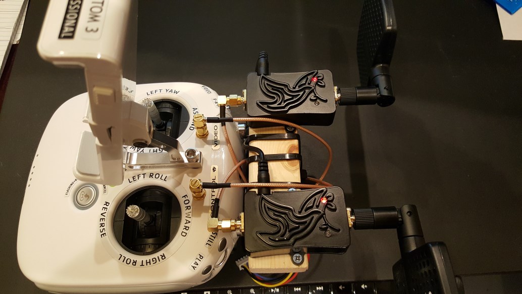
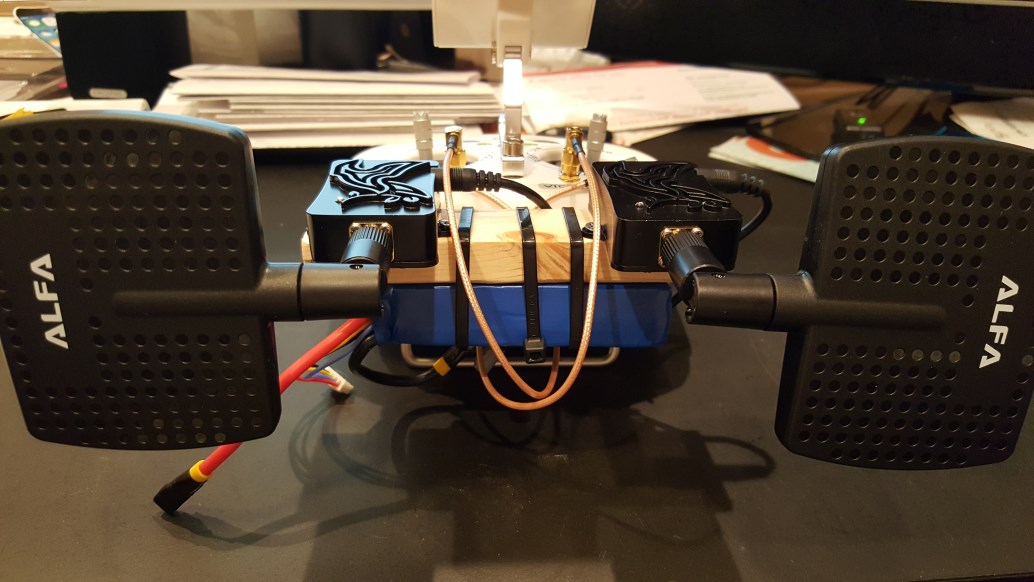
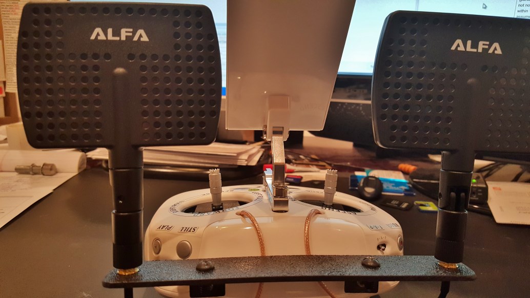
I have added these cheap ones. They actually didn't do much good for me. I still lost out on the video side at the same distance as always. My best has been with the ITELITE DBS-02 antenna with no amps so far. BUT, my homemade windsurfers, store bought windsurfers, Alfa directional antennas, etc. got me about 90% as far. I just need to amplify my video back now. I am already just about at my battery limit though.Add some 4.0A boosters to that rig, and you can get up to 5.8 miles away, maybe farther!
Mark The Droner
Premium Pilot
- Joined
- Aug 26, 2015
- Messages
- 5,404
- Reaction score
- 1,826
You mean like this? Amazon.com: 2.4G 2W Radio Amplifier Module Black for DJI Phantom Walkera 2.4G Transmit Part: Toys & Games...I need to choose the right size amp for video/telemetry back to the remote. I was thinking of one of the little 2.4ghz ones they sell on Hobby King.
Yeah there's a thread on this somewhere...
Yep, that's what I am thinking of. They have a white one on Hobby King for $25.00 or so if I remember right.You mean like this? Amazon.com: 2.4G 2W Radio Amplifier Module Black for DJI Phantom Walkera 2.4G Transmit Part: Toys & Games
Yeah there's a thread on this somewhere...
Similar threads
- Replies
- 11
- Views
- 13K
- Replies
- 3
- Views
- 529
- Replies
- 3
- Views
- 648
- Replies
- 6
- Views
- 2K


Recent Posts
-
 North Jersey, Very new old guy trying to get off the ground with a P330Z Phantom 2
- Latest: captainmilehigh
-

-

-

-
