Phantom 3 Std. Motherboard/ESC failure on power-on - Please Help

Joined
Jan 9, 2019
Messages
14
Reaction score
0
Hello all,

I'm asking for some help here because I'm losing my mind with frustration at what has happened to my drone. Let me explain.

I'm a Phantom 3 Standard owner. I'm also a full time student, so this was a fairly large purchase and something I put a lot of time and research into. I really enjoy flying it and have made the best of my purchase so far. With that in mind, I don't have the money to spend on lots of repairs in the event that something goes wrong, and I certainly can't afford to have DJI do those repairs. Unfortunately, what led me to this point was a cracked shell, which I replaced myself - almost. To be clear, the cracked shell is unrelated other than the fact that it's the reason why I was servicing the drone. This is where things went wrong.

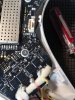
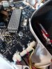
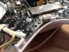
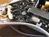
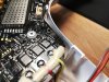
During reassembly, I decided to do a test power-on. I had everything back together except for the top shell (I had the GPS plugged in) and of course, no propellers. I know this probably isn't a recommended way to do a power-on test, but I made sure everything was visually safe before testing. When I turned on the drone, one of the SMD capacitors on the 'M4' corner sparked, leaving small burn marks on the motherboard and shell. I've attached photos for reference. I immediately unplugged everything before just about losing my mind in frustration.

Okay, so I know that most people's response would be "Oh, it's dead. Time to buy another board." But I don't necessarily have the money for that. I'd like to get feedback, if possible, on fixing this board first, before attempting a replacement. If a main Logic chip had blown, I would have scrapped the board by now, but let me explain why I haven't given up on this one just yet.

Here is what I observed relating to the incident:
  • Timing. I think most owners know the startup sequence quite well. (Press then hold power button > wait a second > motors initialize > beeping noise > etc.) The spark occurred as the motors initialized, and before I could unplug the battery, the drone did it's beep. This gives me hope that the whole board isn't fried. The fact that the end of the SMD capacitor is completely gone, it's location on the board, and the fact that it happened as the motors were moving makes me quite sure that's it's an ESC related failure/short.
  • While the SMD capacitor blew apart and made a bit of a mess, It doesn't seem to have physically compromised any surrounding components.
  • Nothing was visually shorting out the capacitor, or the motherboard in general.
So with all of that in mind, here are some thoughts:
  • I still don't have any ideas on what might have caused the short. I may have hit the capacitor while prying the top shell off.
  • If the repair came down to simply replacing the SMD capacitor (which it may not), I have the experience and equipment required to replace it. That assumes i can identify the specs of the capacitor to get another one.
  • Assuming the damage is solely ESC related (which it may not be), If I de-soldered the burned up capacitor and removed any conductors, in theory, I could fire up the drone and check what works or not (of course without working motors). If worst comes to worst, what do I have to lose - an already damaged board? Potentially damaging other sensors...maybe? That may be a bad idea all together.
  • Obviously sparks are nothing to shrug off, but If all it was was a short that caused the damage, might there be a chance that the rest of my board could be okay, since the capacitor blew and disconnected power?
  • If I could get my hands on a schematic for the board, that would really help in determining what else is damaged and what parts I might need.
  • I looked into replacement boards. Like I said, I don't have tons of money to spend and the cheapest board I saw was $90 used. I know that's not a lot, but for a ~$300 drone (with a brand new shell I just bought), I'd like to at least attempt a fix.
  • Going forward, I will probably attempt to remove the blown capacitor and clean the area using proper methods. This would allow me to further identify damage.
So to conclude, here are my questions:
  1. Does anyone have the schematics for this board? Are they even publicly available or attainable? I'm guessing no, but I might as well ask.
  2. Can anyone with experience on circuit layout and this type of stuff give me their thoughts on a potential fix?
  3. Is there a verified place to get replacement boards that don't cost outrageous amounts, if all else fails? Fine with buying used if it's the cheapest option.
  4. Any theories on the potential problem? The drone worked flawlessly before I opened it up.

Anyways, thanks so much for any advice or potential solutions!
- Benji
 

Attachments

  • IMG_20190109_102835.jpg
    IMG_20190109_102835.jpg
    776.6 KB · Views: 2,681
  • IMG_20190109_102842.jpg
    IMG_20190109_102842.jpg
    806.5 KB · Views: 2,353
  • IMG_20190109_113238.jpg
    IMG_20190109_113238.jpg
    745.7 KB · Views: 2,250
  • IMG_20190109_113252.jpg
    IMG_20190109_113252.jpg
    975.8 KB · Views: 2,370
  • IMG_20190109_113334.jpg
    IMG_20190109_113334.jpg
    759.2 KB · Views: 2,274
Last edited:
Sorry for your misfortune? I have a good idea the information is out there. We have some very tech guys on this forum. You Tube might be of some help. If it doesn't have the information you need, the video might lead you to a person that would have the background to know.
Strange how it all happened. I tried to see if there were any kind of markings on it, there aren't.
DSC_5703.jpg
DSC_5705.jpg
DSC_5703.jpg
DSC_5705.jpg
 
  • Like
Reactions: BenjiHoggi
WV. Rootman,

Thanks so much for the response and encouragement. If nothing else, the awesome people on this site will cheer me up.

I've done some scouring of the web, and I've found some more information on the specific part. It seems to be an 0603 size ceramic SMD capacitor. I tried to see if there was a way to identify it, but it seems to be a common fact that it's impossible to identify these little things. Your images really help though, for the fact that they outline the copper traces of the board more clearly than I can see on my own board. I've removed the blown cap from my board, but it made a nice 'crater' and it blew some of the trace out. I think I can solder a new cap on, but that assumes I can get one, and that the same issue won't happen again.

Also, I should mention that I have found these pages that seem to have a list of parts, pictures, and some rudimentary schematics:
o-gs/dji-firmware-tools
o-gs/dji-hardware-schematics

I'm also no expert, so trying to understand these isn't going so well. I've checked YouTube, but honestly, the most helpful information i've found so far has been from browsing this forum.

Benji
 
Some really good reading. You did good. I noticed a similar circuit up from the one that blew in my picture.
Can I use a multi meter to read the capacitor while in the circuit?
 
Had a hard landing with my P3S. Tore the female connector off the mainboard along with some of the trace leads. Don't think you'll have great luck repairing the leads. I was a NASA trained solder and as hard as I tried to do a good repair I just couldn't get the reliability with the reattached leads. I ended up buying a used board on Fleabay for $70. The replacement mainboard works but I'm now limited with distance when flying? The original board could fly over 1 mile but this replacement is limited to about 800'. Still trying to work out this issue. I priced a new mainboard from Cloud City Drones and it was $169. Not convinced yet to spend the money on a $500 A/C. Regardless, good luck with your repair.
 
Some really good reading. You did good. I noticed a similar circuit up from the one that blew in my picture.
Can I use a multi meter to read the capacitor while in the circuit?
I think you're right about the similar circuit, I saw someone else referencing that in another forum post as well, and It makes sense when I look at my board. I think it's a small cluster of components that have been reused throughout the board, which include that capacitor.

I had to scrape some of the clear coating off the terminals, but I did test some of the other identical capacitors for resistance and continuity. I'm not an expert on how to measure capacitors, so these may be absolutely the wrong measurements to get.

Using my Fluke 77 II, I measured the following:
  • Continuity: ~0.758 (not sure what unit) - for every capacitor I found, and also for the terminals of the missing capacitor that blew (which I have removed). They were all the same.
  • Resistance: ~~~5.1kΩ, Hard to tell - Resistance was changing a lot, but for the most part it looked the same for the missing capacitor's pads and for every other capacitor. Within a minute or so, the resistance would stop dropping at roughly 5.1kΩ.
Neither of these tell me much other than the fact that they're very similar for every other capacitor on the board. They may also be effected by the fact that there seems to be that other small component parallel to the big capacitor that blew, which might be keeping the numbers consistent between "clusters".

Maybe someone else can offer some explanations for these numbers. A board schematic with component values would give me reason to test more, but for now, all i have to go off of are similar components on the board in other places to test and compare with.

Had a hard landing with my P3S. Tore the female connector off the mainboard along with some of the trace leads. Don't think you'll have great luck repairing the leads. I was a NASA trained solder and as hard as I tried to do a good repair I just couldn't get the reliability with the reattached leads. I ended up buying a used board on Fleabay for $70. The replacement mainboard works but I'm now limited with distance when flying? The original board could fly over 1 mile but this replacement is limited to about 800'. Still trying to work out this issue. I priced a new mainboard from Cloud City Drones and it was $169. Not convinced yet to spend the money on a $500 A/C. Regardless, good luck with your repair.
Thanks for the feedback, that gives me some idea of pricing for these boards. My P3S never went farther than ~1000-1500ft without losing connection, though that was with trees around and I didn't always have line of sight. Before all of this mess, I was going to buy an ARGTek range extender kit for my controller to remedy the issue somewhat, but of course, that won't be happening now.

Benji
 
I think you're right about the similar circuit, I saw someone else referencing that in another forum post as well, and It makes sense when I look at my board. I think it's a small cluster of components that have been reused throughout the board, which include that capacitor.

I had to scrape some of the clear coating off the terminals, but I did test some of the other identical capacitors for resistance and continuity. I'm not an expert on how to measure capacitors, so these may be absolutely the wrong measurements to get.

Using my Fluke 77 II, I measured the following:
  • Continuity: ~0.758 (not sure what unit) - for every capacitor I found, and also for the terminals of the missing capacitor that blew (which I have removed). They were all the same.
  • Resistance: ~~~5.1kΩ, Hard to tell - Resistance was changing a lot, but for the most part it looked the same for the missing capacitor's pads and for every other capacitor. Within a minute or so, the resistance would stop dropping at roughly 5.1kΩ.
Neither of these tell me much other than the fact that they're very similar for every other capacitor on the board. They may also be effected by the fact that there seems to be that other small component parallel to the big capacitor that blew, which might be keeping the numbers consistent between "clusters".

Maybe someone else can offer some explanations for these numbers. A board schematic with component values would give me reason to test more, but for now, all i have to go off of are similar components on the board in other places to test and compare with.


Thanks for the feedback, that gives me some idea of pricing for these boards. My P3S never went farther than ~1000-1500ft without losing connection, though that was with trees around and I didn't always have line of sight. Before all of this mess, I was going to buy an ARGTek range extender kit for my controller to remedy the issue somewhat, but of course, that won't be happening now.

Benji
The continuity and resistance checks are only useful to check if the capacitor is shorted internally- they are no use to determine the capacitance. You need a capacitance meter and in most cases the component will need to be taken out if circuit to test.
 
The continuity and resistance checks are only useful to check if the capacitor is shorted internally- they are no use to determine the capacitance. You need a capacitance meter and in most cases the component will need to be taken out if circuit to test.
That would make sense to me, thanks for clarifying.

I think in terms of identifying the capacitor's specifications, It's not sensible for me to spend money on such a device when I have no guarantee that replacing the capacitor will even fix the board. If someone had a donor board and could identify the component or send me one for cheap, I'd be happy to try that. But otherwise, I might as well put my money towards a new board. I wouldn't imagine it would be hard for someone with a dead board to get me the part, I just don't know where to find that. If anyone can aid me here, that would be amazing.

I think my idea around measuring continuity and resistance was meant to try and aid me in figuring out whether other components were also blown out. But I haven't gotten very far on that so far.

Benji
 
Had a hard landing with my P3S. Tore the female connector off the mainboard along with some of the trace leads. Don't think you'll have great luck repairing the leads. I was a NASA trained solder and as hard as I tried to do a good repair I just couldn't get the reliability with the reattached leads. I ended up buying a used board on Fleabay for $70. The replacement mainboard works but I'm now limited with distance when flying? The original board could fly over 1 mile but this replacement is limited to about 800'. Still trying to work out this issue. I priced a new mainboard from Cloud City Drones and it was $169. Not convinced yet to spend the money on a $500 A/C. Regardless, good luck with your repair.
I have a friend who is an AUDI trained mechanic but he couldn’t fix my cheap Chinese genset.

Trying to repair current Electronics with SMD and lead free fabrication processes presents new challenges.
 
That would make sense to me, thanks for clarifying.

I think in terms of identifying the capacitor's specifications, It's not sensible for me to spend money on such a device when I have no guarantee that replacing the capacitor will even fix the board. If someone had a donor board and could identify the component or send me one for cheap, I'd be happy to try that. But otherwise, I might as well put my money towards a new board. I wouldn't imagine it would be hard for someone with a dead board to get me the part, I just don't know where to find that. If anyone can aid me here, that would be amazing.

I think my idea around measuring continuity and resistance was meant to try and aid me in figuring out whether other components were also blown out. But I haven't gotten very far on that so far.

Benji
Without looking at the circuit in detail we can safely assume any small ceramics around the ESC inverter stage will perform bootstrapping for the mosfet gate or filtering (they are too low in value to act as a reservoir). There is a high probability that the failure indicates another component failed- to find one or more of the mosfets has died wouldn’t be a surprise.

Question is why? You could have a short in a motor feed or the board was damaged in the crash. I would be checking the motors before powering up another board.
 
I don't completely understand what you mean about bootstrapping. Are you saying that the ceramics provide protection for the ESC in some form? And I would assume that something else failed, possible an mosfet, but is there any way for me to know? I know where the mosfets are and what they look like.

I'd also like to be clear here. I was not fixing the drone because of a crash, I was replacing the shell as a result of cracks that had formed from a hard landing I had a fairly long time ago (so I guess it's indirectly because of a crash). The drone functioned flawlessly up until the point where I disassembled it and replaced the shell. With that in mind, In my opinion, something I did during that disassembly/reassembly process caused the board to spark and fail. I do remember hitting something when prying off the top shell, and it might have been the motherboard. I don't see any physical scrape damage or anything like that though.

Your point about checking the motors totally makes sense though. I assume I could just find their voltages and safely plug them into a proper voltage DC power source to test them, after I disconnect them from the board of course. Would there also be any sense in powering on the drone to test the board with the capacitor disconnected, or is that just an accident waiting to happen? I would guess so, but i don't know what I have to lose here.

Benji
 
I had another random thought. Since it seems like the LED boards are also connected to the ESCs for power, could it remotely be a possibility that I shorted one of the LED boards or something like that when I was hot gluing them back in place?

Benji
 
If everything was in place when you finished, how could there be a short unless the battery was in while you were hot gluing? I don't know.

In one of the sites that you posted, I was reading that a capacitor and a resistor step the voltage up to 46 volts to run the LED's. That caught my eye, because I'm playing around with jewel thief circuitry. It's a circuit that takes a dead battery bumps the voltage up to be able to run the LEDs with next to no current. It is very efficient and runs the LED'S for a very long time. That may be what blew if the LEDs did short. That capacitor and resistor circuit.
Sorry, I just rambling now. I haven't a clue.
You're probably right. Just thought I would ask.

And don't worry, any suggestions or feedback at all is appreciated. It seems like i'm probably at the end of the line for this board. I suppose I'll put the project off until a later time when I have the money to fix things.
 
One more general question I have is this. Does anyone think that the board shorting could have caused damage to any other components like the camera or other sensors, given the location of the blown part? If so, I'd probably just sell the thing for scrap and move on with my life. I'd be in almost the value of the drone for a new camera AND a new board. That would be super sad but it makes the most sense for me if that is the case.

Thanks overall for the help and suggestions.
Benji
No
 
You might reach out to Thunderdrones to get an estimate...... it wouldn't hurt to ask. Thunderdrones Repair Information
Thank you for your suggestion. I am currently planning to repair the drone myself because it's my cheapest option, but I did take a good look at their services and pricing and it looks very reasonable.


So currently, I think I've given up on any chance of fixing my current board. I'll hold onto it in case I might need anything from it in the future. It's good to have spare parts. I don't want to even try to fix it and risk blowing more things up like my camera if my fix fails or something else is dead too.

Right now, i'm looking at buying a lightly crashed but fully functional P3S from an eBay seller who sells a lot of them. Getting the whole drone (no accessories) for under $100 is the same price as getting a used board alone on eBay, at least right now. It's more risky, I know, but I'll also get all the LED's, motors and extra parts, and the guy accepts returns. I can at least sell the motors and LED's to recoup some of my losses. Does anybody have any thoughts on viability of parting out these drones and part pricing these days?

Thanks!
Benji
 
Quick Update just for the sake of 'resolving' my original issue and answering my questions.

I've bought a crashed P3S for $80 on eBay with 60 day returns. The guy who was selling it also apparently test flew it. Great deal if you think about it - a lightly damaged, tested quad with no accessories and returns accepted for the price of a used board. I'd be happy to link the guy's store on eBay if anyone is interested - DM me. He's got like 10 other quads for sale atm.

Anyways, I swapped the whole motor/LED/Motherboard assembly into my drone and it flew flawlessly other than a faulty compass sensor. I was having some awful jello effect from some vibrations, so now i've even solved that with the new motors! (I think) I'll still have to test everything thoroughly of course.

Going forward, i'll probably try and sell all the working good condition parts from the crashed drone as well as stuff I didn't use from mine. I'm hoping to make at least a bit of my money back. So I guess to answer my own question for anybody who might be facing a similar problem, fixing a blown board outright isn't probably feasible for the average joe like me. Buying a semi-functional crashed drone may be the way to go if you can do the work yourself. I may or may not update this thread with my parting-out results, depending on how well that goes.

Anyways, thanks for all the help and suggestions, this community is awesome!
Benji
 
How do you know the supposed failed 0603 part is a capacitor vs. a resistor if unmarked? I only have the schematic for the older P2V+ ESC, though probably quite similar to the newer Phantoms. Only so many ways to get those motors to spin. The MOSFETs gets its drive pulses from a microprocessor controller chip, which in turn energizes the motor windings in sequence. Only resistors in that circuit for setting the MOSFET gate drive levels and voltage sensing (to verify the motors are spinning). Only a few 0.1uf and 1.0uF capacitors on the voltage bus and a voltage regulator output. If you have any electronic skills at all, I would recommend seeing where the failed device traces goes to. Probably to one of the MOSFET ICs. Knowing the pin number and markings on the MOSFET chip could help determine its function. A spark in unsettling. As others have said, that would be caused by a short further down the line (like the motors or wiring), or perhaps that component wasn't soldered correctly on one side making it spark when you applied the heavy load of the motors. Capacitors on the ESC are used primarily for smoothing out the DC voltage on the battery buss from the motor pulses. I would unsolder that component in the event it is shorted out and carefully power it up again. If a failed capacitor, that should not effect how the motors are driven. If a failed resistor, it would alter the gate bias on ONE of the MOSFETs, making ONE of the motors spin with a hiccup. The only real way to know if the motors are getting the proper drive pulses, proper voltage and sequence is to use an oscilloscope. A DVM won't tell you much unless one of the three wires is zero volts. Good luck and let us know what you find.
 
  • Like
Reactions: BenjiHoggi

Members online

Forum statistics

Threads
143,066
Messages
1,467,355
Members
104,934
Latest member
jody.paugh@fullerandsons.