- Joined
- Oct 3, 2016
- Messages
- 6
- Reaction score
- 1
- Age
- 27
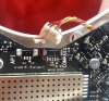
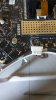
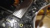
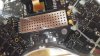
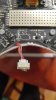
My compass wasn't working after a crash so I opened up my phantom only to find the compass connector completely broken off. I tried soldering some wire to it but it seems the metal plates that were one the actual PCB were completely ripped off. Is there any way to solder this back together. Or do I have to bite the bullet and buy a hole new board .

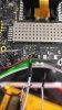

 !!! After that, it doesn't have any problem until now (have flied dozen times with perfect condition).