Yes, I remember. You need to re look at the sensors on the yaw motor. Most of the yaw motors that are sold on EBay are from crashed drones. over 50% have scratched sensors. Use a 25 x magnifying glass to inspect them. Any marks on the sensors and it is trashed. Also if you change the esc board on the back of the yaw arm it may cause the same problem as it is not calibrated to the casing on the yaw motor, The esc board and the casing are a set.


You are using an out of date browser. It may not display this or other websites correctly.
You should upgrade or use an alternative browser.
You should upgrade or use an alternative browser.
P4 Gimbal Yaw Problem
- Joined
- Nov 16, 2015
- Messages
- 876
- Reaction score
- 337
- Age
- 66
Thanks for reply gee I did not know that the esc board and the casing are set..might have to put original esc board back in camera?Yes, I remember. You need to re look at the sensors on the yaw motor. Most of the yaw motors that are sold on EBay are from crashed drones. over 50% have scratched sensors. Use a 25 x magnifying glass to inspect them. Any marks on the sensors and it is trashed. Also if you change the esc board on the back of the yaw arm it may cause the same problem as it is not calibrated to the casing on the yaw motor, The esc board and the casing are a set.
yes, it is calibrated to the original casing. Only DJI has the equipment to calibrate the ESC board. They are keeping it a secret
- Joined
- Nov 16, 2015
- Messages
- 876
- Reaction score
- 337
- Age
- 66
Hey Ted these P4 gimbals can make a man go grey real quickThanks for reply gee I did not know that the esc board and the casing are set..might have to put original esc board back in camera?
yes, it is calibrated to the original casing. Only DJI has the equipment to calibrate the ESC board. They are keeping it a secret
Hola, tengo el mismo problema con el motor de guiñada, cambié el motor de guiñada y usé la carcasa del motor original pero me sigue el mismo problema, no sé si los sensores magnéticos también están defectuosos, no tienen ningún rasguño y aun así no duelen centraron la cámara sino a la izquierda. help me!!!!!He estado en este camino. No se centrará a menos que utilice la carcasa del motor de guiñada original. El sensor está calibrado para las ubicaciones de sus imanes. Dji nos jodió con esto. Reemplazar el motor de guiñada no es una cura.
¿Puedes enviarme un video para que pueda ver este problema?Hola, tengo el mismo problema con el motor de guiñada, cambié el motor de guiñada y usé la carcasa del motor original pero me sigue el mismo problema, no sé si los sensores magnéticos también están defectuosos, no tienen ningún rasguño y aun así no duelen centraron la cámara sino a la izquierda. help me!!!!!
can you send me a video so I can see this problem?
¿Puedes enviarme un video para que pueda ver este problema?
¿pueden enviarme un video para que pueda ver este problema?
¿Puedes enviarme un video para que pueda ver este problema?
¿pueden enviarme un video para que pueda ver este problema?

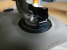
There are no digital sensors with hysteresis in the drone gimbal motors, only analog ones. Hall sensors here are not for switching, windings, but for determining the angle. It is necessary to measure the magnetic field very accurately. The signal difference from the two sensors makes it possible to determine the position of the chamber angle within the size of one rotor magnet. The sensors are not afraid of scratches, but any displacement or replacement of magnets disrupts the system setup.
Sensor is DRV5053 Analog-Bipolar Hall Effect Sensor.
The two sensors are placed symmetrically opposite the magnets when the camera is facing forward. Their signals must be equal. But the magnets cannot be made so uniform and it is impossible to place the sensors perfectly exactly between the teeth of the stator so that the current of the windings does not affect the readings. Correction made in the control module.
Last edited:
I have found that light scratches are ok but I am thinking that when they get scratched, they may get metal filings on the Hall sensor. I have cleaned them with acetone and they worked. Most of the time I just replace the Hall sensor or the motor. The old drum has to be reused. I have a couple hundred drums. I would like to find a way to identify where the magnets are located in the casing. I have to swap them out until I find one that centers. I only have to do this if the original casing is damaged or lost.
I have found that light scratches are ok but I am thinking that when they get scratched, they may get metal filings on the Hall sensor. I have cleaned them with acetone and they worked. Most of the time I just replace the Hall sensor or the motor. The old drum has to be reused. I have a couple hundred drums. I would like to find a way to identify where the magnets are located in the casing. I have to swap them out until I find one that centers. I only have to do this if the original casing is damaged or lost.
Phantom 4 yaw motor broken! plz help
Yes it's You legand! Thanks and if I may ask with just the roll motor is it a simple old one off and new one on?? a straightforward swap. There are a number of YouTube videos you should look at. 15 mins tops you're done with the swap. Just have the right tools
 phantompilots.com
Yes just a swap. However it may lay to one side before straightening up. If you don’t want it to do that, swap the casing out for the original just like with the yaw.
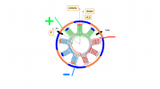
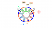
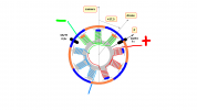
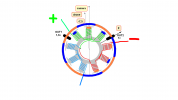
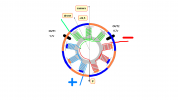
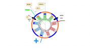
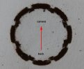
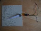
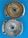
There are six options for supplying voltage to the motor. The current will flow through the 6 teeth of the windings. They will stand symmetrically opposite 6 magnets. The center of forces is marked with the letter F. The mounting angle is easily calculated. In the sector we need, there will be 6 camera positions. I connected the hall sensors to a multimeter and recorded the output signals for each of these positions. The diagram shows the "correct" voltages. On a real magnet it may be different. For example, a Hall sensor between two magnets should output exactly 1 volt. If this is not the case, either the magnet is defective or the sensor is misaligned from the ideal position. This turned out to be with me, after soldering the sensor, the situation was corrected. The last photo is magnetic powder sprinkled on paper, under which the magnetic system.
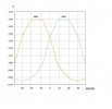
For visualization, I made a graph of signals from sensors depending on the angle of the yaw motor. This graph repeats every 45 degrees (we have 8 magnets). If the camera deviates more than 37.5 degrees, it will jump to another sector and the camera will look at the drone's support. I limited the deflection angle to 30 degrees. I just glued thin elastic bands like stops. Drone calibration accepted it!
For visualization, I made a graph of signals from sensors depending on the angle of the yaw motor. This graph repeats every 45 degrees (we have 8 magnets). If the camera deviates more than 37.5 degrees, it will jump to another sector and the camera will look at the drone's support. I limited the deflection angle to 30 degrees. I just glued thin elastic bands like stops. Drone calibration accepted it!
Attachments
Last edited:
Continuation.
The extreme positions of the camera do not always coincide with the extreme positions of the magnetic system of the motor. This is one reason why the camera suddenly looks at the drone's cradle and the controller reports gimbal motor overload. Turn the camera left and right (do not turn on the drone!) The drone legs should not be in the camera's field of view. In the photo there are limiters that are easy to stick on. Also a photo of how to build a stand for testing Hall sensors and checking the motor (if you have an 8 volt brushless motor speed controller, you can see how the motor works)
The extreme positions of the camera do not always coincide with the extreme positions of the magnetic system of the motor. This is one reason why the camera suddenly looks at the drone's cradle and the controller reports gimbal motor overload. Turn the camera left and right (do not turn on the drone!) The drone legs should not be in the camera's field of view. In the photo there are limiters that are easy to stick on. Also a photo of how to build a stand for testing Hall sensors and checking the motor (if you have an 8 volt brushless motor speed controller, you can see how the motor works)
Attachments
Hello,
We are having a problem with P4 camera getting stuck in either left or right side.
To start, we are drone and RC shop and repair service, we have sold, fixed and tested anything DJI and many more has to offer.
But now we are facing this challenge. The camera is getting stuck to one side. The IMU calibration, Auto-calibration, pulling camera to one side DOES NOT WORK.
Manual options for gimbal are there to fine tune the position of the camera, so they don't work in this case.
The problem was that the thing went viral on us. One P4 came with that issue. By trying to put finger on the problem, we started replacing parts of the gimbal with the parts from the gimbals we work well.
The problem escalated when we replaced the back board of the camera.
We took the board from the working gimbal, placed it on the troublesome one, concluded that it doesn't' help, and placed it back.
The working gimbal suddenly started acting crazy, rotating (the yaw axis) camera to one side.
We took entire gimbal and placed it to a fully functioning P4 and it still pulled to one side.
We took the back board of the camera from working one, placed it to the pulling-to-one-side P4 and saw that it also pulls to the same side.
We returned it to its original P4 and then it started pulling to the other side.
We haven't tried to replace the flat cable, we tried replacing the entire camera from the working gimbal without success.
The IMU calibration (cold, warm, flat surface), gimbal calibration, yaw adjustment, firmware downgrade, upgrade, rotating gimbal to one side manually, change of aforementioned parts, (vitamins C, lot of sunshine, jiggling the cord, ctrl+alt+del, fresh air, magic words, quoting Harry Potter...) doesn't work.
Has anyone got any similar problem that they managed to get fixed?
The final measure would be returning it to DJI, but being a repair shop that rarely fails to fix them, we would appreciate any insight that might help us.
I may have failed to mention some of the fixing procedures we tried, but let us know your thoughts and we remember them.
The image shows one of the problems. There are worse than that.
Thank you.
Try the legs up calibration. If that doesn’t work your going to unfortunately start swapping yaw motor hubs until you get the right one. Definitely put the original ESC board back in because the roll motor as well as the yaw motor are paired to it. The pitch motor is paired to the board in the camera
Photo taken after testing. So the wires lead nowhere. A motor test is required if it is suspected that it has burned out or the magnets are damaged. I used a Hobbywing Skywalker 2-6S 80A UBEC Brushless ESC and a servo tester, applied 8 volts. This is not on the photo. Hall sensors are not needed.
I have an extra ESC from a Phantom 4 with a connector for the yaw motor. All wires are soldered there. If you find such a connector in old electronics, use it. It's hard to do this without a microscope.
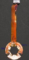
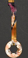
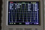
The sensors use 5 wires. Everything is marked in the photo below. To test them, you can apply 3.3 volts (more than 20 volts, according to the datasheet). The sensor has a built-in stabilizer. the output signal is measured by the tester. As a bonus, I am attaching a photo from the oscilloscope - a signal from one sensor when the motor is running. Ideally, all waves are equal on both sensors.
There is a chart in the previous post. This "butterfly" should be symmetrical.
I have an extra ESC from a Phantom 4 with a connector for the yaw motor. All wires are soldered there. If you find such a connector in old electronics, use it. It's hard to do this without a microscope.
The sensors use 5 wires. Everything is marked in the photo below. To test them, you can apply 3.3 volts (more than 20 volts, according to the datasheet). The sensor has a built-in stabilizer. the output signal is measured by the tester. As a bonus, I am attaching a photo from the oscilloscope - a signal from one sensor when the motor is running. Ideally, all waves are equal on both sensors.
There is a chart in the previous post. This "butterfly" should be symmetrical.
Attachments
You can fool the system, but the drone doesn't fly upside down.Try the legs up calibration. If that doesn’t work your going to unfortunately start swapping yaw motor hubs until you get the right one. Definitely put the original ESC board back in because the roll motor as well as the yaw motor are paired to it. The pitch motor is paired to the board in the camera
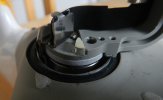
The photo shows a motor with neodymium magnets. The signals from the sensors are ideal. I do not want to disassemble the drone to check in operation. Obviously the yaw motor moves maximum weight and must be strong.
Attachments
actually the upside calibration works for some issues. After the upside down procedure you have to do it again right side up.
Similar threads
- Replies
- 14
- Views
- 3K
- Replies
- 9
- Views
- 8K
- Replies
- 2
- Views
- 1K
- Replies
- 9
- Views
- 8K


Recent Posts
-
-
 North Jersey, Very new old guy trying to get off the ground with a P330Z Phantom 2
- Latest: captainmilehigh
-

-

-
