Fixing flash in DM365 chip within Ph3 Pro gimbal

My output from the console:
Code:
root@Dji-Pro:~# mount /dev/sda
mount: can't find /dev/sda in /etc/fstab


If you copy and paste a command, try to use the whole line. If you don't know how to use a command, google it, ie. "man mount".

If 'mount' gets only one param, it searches for the rest in 'fstab'.

I follow the steps of the wiki and I stay in the ubi file part. input output error

Unsupported file system on the USB drive?
 
  • Like
Reactions: GUCCI40
I never had damaged Ambarela. From the Wiki:
o-gs/dji-firmware-tools
And sub-wiki about m0100:
o-gs/dji-firmware-tools
you can conclude that yes, you should always get the log if you connect to U0_* pins.


If you see binary data, that might be an interface with internal communication between the drone components. You can capture the communication by this tool:
o-gs/dji-firmware-tools

These are interesting findings; I don't think anyone looked into these interfaces in detail. If you can capture the binary packets, I'd be interested in looking at them.
[/QUOTE]
HI,

Thanks for very helpful post. I have stuck on step 5.
My system says that it cannot find sda device. Any Advices?
I formated miniSD card ant put into gimbal port. I have copier there ubi file too in the root directory.

My output from the console:


root@Dji-Pro:~# mount /dev/sda
mount: can't find /dev/sda in /etc/fstab
root@Dji-Pro:~# more /etc/fstab
# stock fstab - you probably want to override this with a machine specific one

rootfs / auto defaults 1 1
proc /proc proc defaults 0 0
sysfs /sys sysfs defaults 0 0
devpts /dev/pts devpts mode=0620,gid=5 0 0
#usbfs /proc/bus/usb usbfs defaults 0 0
tmpfs /var/volatile tmpfs defaults,size=16M 0 0
tmpfs /dev/shm tmpfs mode=0777 0 0
#tmpfs /media/ram tmpfs defaults,size=16M 0 0

# uncomment this if your device has a SD/MMC/Transflash slot
#/dev/mmcblk0p1 /media/card auto defaults,sync,noauto 0 0
root@Dji-Pro:~#

I did not see many plates either, the Ambarella were only damaged by spare flex of low quality that sent 15 v to the sensor inputs, the simtom is to overheat and decrease in the impedance of the sensor inputs. Changing the subject I leave the chip images nand cracked or the pressure of the gimbal arm in the falls. Greetings friends.
 

If you copy and paste a command, try to use the whole line. If you don't know how to use a command, google it, ie. "man mount".

If 'mount' gets only one param, it searches for the rest in 'fstab'.


Unsupported file system on the USB drive?

I LEAVE THESE PHOTOS TO COMPLETE EVEN MORE THIS EXCELLENT THEME OF THE FRIEND QUDDAMAGE, SEE THE NAND CHIPS, THE TYPICAL FISSURE, IN THE ORIGINAL CHIP YOU CAN NOTICE VERY VERY LITTLE BREAKING IN ANOTHER PHOTO COMPLETE THE DETACHMENT, ALL THE CHIPS ARE BREAKING EXACTLY THE SAME , OBVIOUS ONLY IN PH 3 PRO.

WHEN THE BALLS EXERCISE RESION ON THE PLATE, DAMAGE THE WELDING PADS THAT ARE EASILY DISCHARGED IN SOME CASES, WELDING THIN THREADS CAN RESTARUATE THE FUNCTION WITH A NEW CHIP. I ONLY MISS ME TO BE CAREFUL TO CHARGE ALL THE PARTITIONS IN THE NEW CHIP, THEME THAT I STILL CAN NOT ACHIEVE WE ARE CLOSER THANKS TO THIS BLOG.
 

Attachments

  • 20170825_230111.jpg
    20170825_230111.jpg
    205.9 KB · Views: 734
  • 20170825_230212.jpg
    20170825_230212.jpg
    1 MB · Views: 812
  • 20170929_163114.jpg
    20170929_163114.jpg
    466.5 KB · Views: 842
  • 20171221_020356.jpg
    20171221_020356.jpg
    1.2 MB · Views: 1,096
  • 20171221_020542.jpg
    20171221_020542.jpg
    1.2 MB · Views: 878
  • 20171221_020630.jpg
    20171221_020630.jpg
    671.9 KB · Views: 921
Last edited:
  • Like
Reactions: quaddamage

If you copy and paste a command, try to use the whole line. If you don't know how to use a command, google it, ie. "man mount".

If 'mount' gets only one param, it searches for the rest in 'fstab'.


Unsupported file system on the USB drive?
Ok, i format the card in, Fat , Fat32 and ex FAT error persist, all other poartitions load OK, only UBI is the problem, check de VCC suply re forced suply, me sistema win 64 bit,


I should try on a 32 bit or XP system. I'm rehearsing on a plate with the dead ambarella, I do not think it's the cause, I could try on a plate with ambarella well. regards!
 
Ok, i format the card in, Fat , Fat32 and ex FAT error persist, all other poartitions load OK, only UBI is the problem, check de VCC suply re forced suply, me sistema win 64 bit,

I should try on a 32 bit or XP system. I'm rehearsing on a plate with the dead ambarella, I do not think it's the cause, I could try on a plate with ambarella well. regards!

You did everything I can think of. If the image just won't load from USB drive, then load it via yModem (using 'lrz'):
lrz(1) - XMODEM, YMODEM, ZMODEM

The lrz/lsz tools are available on the Recovery Root Filesystem from here:
o-gs/dji-firmware-tools
 
You did everything I can think of. If the image just won't load from USB drive, then load it via yModem (using 'lrz'):
lrz(1) - XMODEM, YMODEM, ZMODEM

The lrz/lsz tools are available on the Recovery Root Filesystem from here:
o-gs/dji-firmware-tools

I appreciate, I really do not know the use of LRZ or / tmp, which speaks the wiki. I think I can have an error when trying via USB, my question: I copy the UBI file directly into the root of the SD?, should it have a specific name? or contain in a specific subfolder? I did a test with an empty folder inside called "sacard" and the mount worked but still did not read the ubi file. If you can indicate me the exact preparation of the SD name of the same or sub directory. and if I would not thank you very much, the command line to send it via searal with the LRZ and where I should locate the .ubi file in windows. many thanks.
 
I think I can have an error when trying via USB, my question: I copy the UBI file directly into the root of the SD?, should it have a specific name? or contain in a specific subfolder?

Having it in root just makes it easier to type the path. You can really use any file name and any directory you want.


I did a test with an empty folder inside called "sacard" and the mount worked but still did not read the ubi file. If you can indicate me the exact preparation of the SD name of the same or sub directory.

I placed the downloaded .ubi image in root directory of sd-card, without any renaming. Then (if I remember correctly..) I used the exact same commands which are on the wiki:

Code:
cd /tmp; mkdir sdcard
mount /dev/sda sdcard
ubiformat /dev/mtd2 --sub-page-size=512 --vid-hdr-offset=2048 -f sdcard/dm365_root_ubifs.ubi

All commands were successful, no errors.

I only had issues when I thought I'm smarter and diverged from the wiki instructiions, ie. tried to not use recovery root filesystem.

the command line to send it via searal with the LRZ and where I should locate the .ubi file in windows.

I did not used that method, so I can't provide you with full instruction. What I would do is:
1. Install "PuTTY Extra"
2. Run PuTTY, connect to the board,
3. Start the board with recovery root filesystem
4. go to temp folder:
Code:
cd /tmp
5. Make sure tmp is a ramdisk, ie. check the line with "\tmp" in the output of command:
Code:
mount
6. transfer the image - run:
Code:
lrz --ymodem -b
then select ymodem transfer from PuTTY menu and select file to send.
7. Flash it
Code:
ubiformat /dev/mtd2 --sub-page-size=512 --vid-hdr-offset=2048 -f dm365_root_ubifs.ubi

If something does not work, check documentation of the problematic command. You can't do it without understanding what you're doing.
 
Having it in root just makes it easier to type the path. You can really use any file name and any directory you want.


I placed the downloaded .ubi image in root directory of sd-card, without any renaming. Then (if I remember correctly..) I used the exact same commands which are on the wiki:

Code:
cd /tmp; mkdir sdcard
mount /dev/sda sdcard
ubiformat /dev/mtd2 --sub-page-size=512 --vid-hdr-offset=2048 -f sdcard/dm365_root_ubifs.ubi

All commands were successful, no errors.

I only had issues when I thought I'm smarter and diverged from the wiki instructiions, ie. tried to not use recovery root filesystem.


I did not used that method, so I can't provide you with full instruction. What I would do is:
1. Install "PuTTY Extra"
2. Run PuTTY, connect to the board,
3. Start the board with recovery root filesystem
4. go to temp folder:
Code:
cd /tmp
5. Make sure tmp is a ramdisk, ie. check the line with "\tmp" in the output of command:
Code:
mount
6. transfer the image - run:
Code:
lrz --ymodem -b
then select ymodem transfer from PuTTY menu and select file to send.
7. Flash it
Code:
ubiformat /dev/mtd2 --sub-page-size=512 --vid-hdr-offset=2048 -f dm365_root_ubifs.ubi

If something does not work, check documentation of the problematic command. You can't do it without understanding what you're doing.
genius genius! I have no way to thank you, perfect charge via, serial with those commands, I will continue testing, since I have part via USB and serial part, Kernels I can not via serial, do not start, they send but do not start, I'm sure there is something with the locations in the nand I copy as the wiki example says mw.b 0x80008000 0xFF 0x460000, it does not start, by perfect USB, I see that it is more specific in the example locations Dji-Pro # nand erase 0x04a0000 0x460000 Dji-Pro # nand write 0x80008000 0x04a0000 0x460000 funcipna perfect via usb and the UBI does not load by USB but if by serial with your commands, possibly some hardware or system on the PC, tomorrow I will test on a full board to see if the FPV thank you very much and we are still in touch, for the moment I could provide the photos of the Phantom 4 gimbal fail and board Hi res pics
 
Sure, please upload them somewhere.
ok indicate me how I charge them and where you want them. I still do not understand well upload images directly in the texts here. suni those of the broken chip but they were as attachments if you want to arm the publication, I send them to you by mail. the commentaries I send them translated but you can perfect them since the process is not perfect. Many greetings we are in contact.
 
Here is a success story I wanted to share.

I had a Phantom 3 Pro gimbal which didn't allowed me to see the FPV feed. Photos and movies were recorded on sd-card, there was just no live video - only grey background - in Dji Go.

By connecting another gimbal, I narrowed down the problem to gimbal itself - a different gimbal (which had the same firmware installed) worked fine.

If you need to diagnose the cause of your issue, do not just assume it's the same as described here; to through the diagnosis graph to find your cause:
Fix no video feed / black screen / no image transmission / no FPV on Ph3 Pro


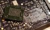
Then I disassembled the gimbal. I looked at available information about the board:
WM320 Gimbal top board · mefistotelis/phantom-firmware-tools Wiki · GitHub

On the schematic, video feed is encoded by media processor model DM365:
dji-hardware-schematics/phantom_3_pro_overview.pdf at master · mefistotelis/dji-hardware-schematics · GitHub

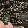
To check whether the media processor is working correctly, I tapped to UART interface of the DM365 chip with TTL-to-USB converter (aka FTDI). See here for details:
Firmware m0800 · mefistotelis/phantom-firmware-tools Wiki · GitHub

I opened PuTTY on the interface before connecting 5V power for the board, then connected the power. There was no output on the console while the board was booting. But the board was booting - I was able to see the diode blinking on it. Which means either my FTDI configuration was bad, or the chip just wasn't producing any output.

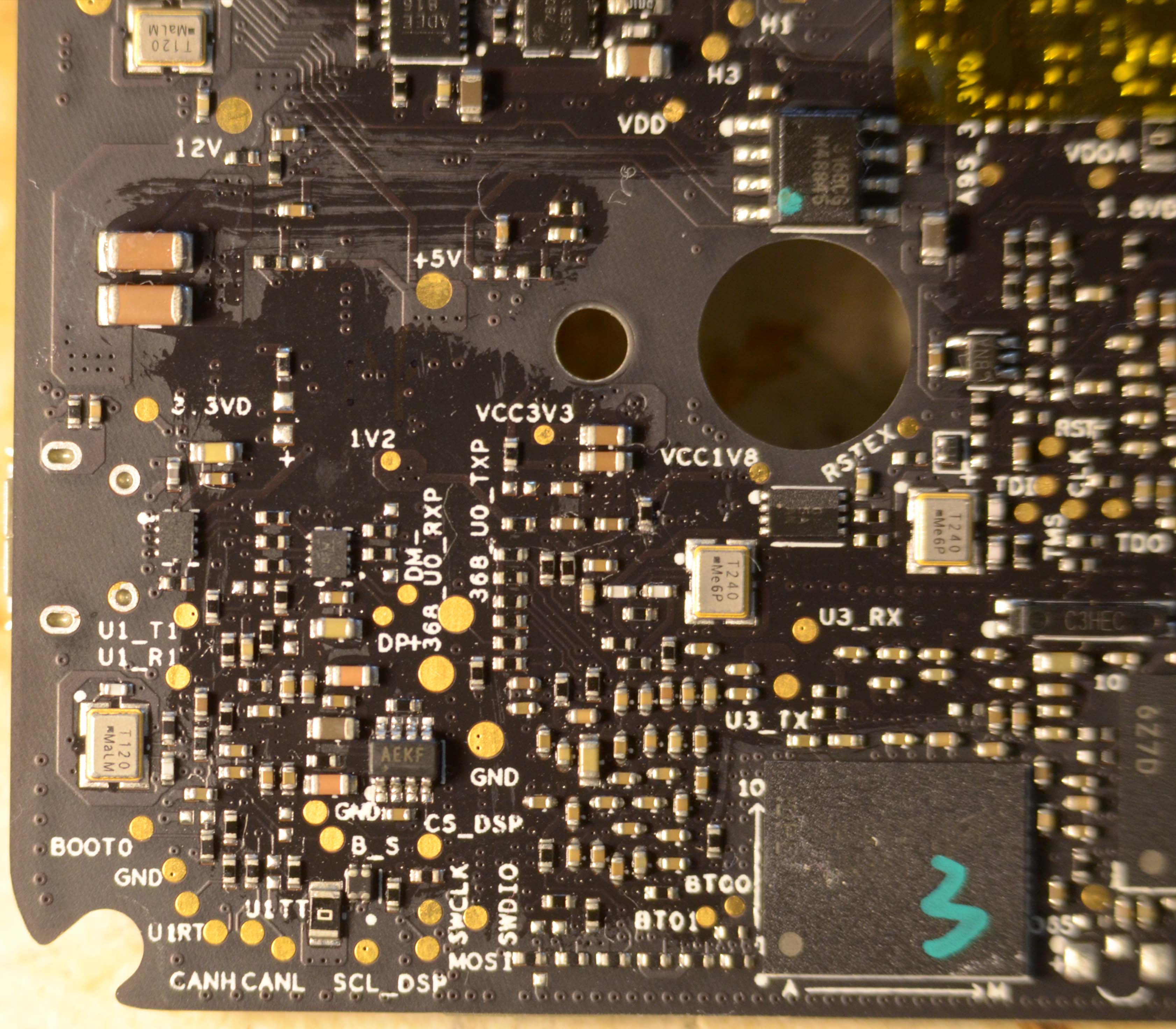
To check which is true (and also fix the issue if this turns out to be a chip boot issue), I shorted the boot pins to 3.3V and connected the board to PC again. This should cause the DM365 chip to boot internally, without use of NAND. This time I was able to see a series of "BOOTME BOOTME BOOTME" messages. This ment my FTDI configuration is fine, the DM365 chip really wasn't printing anything when trying to boot from NAND.

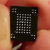
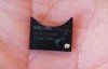
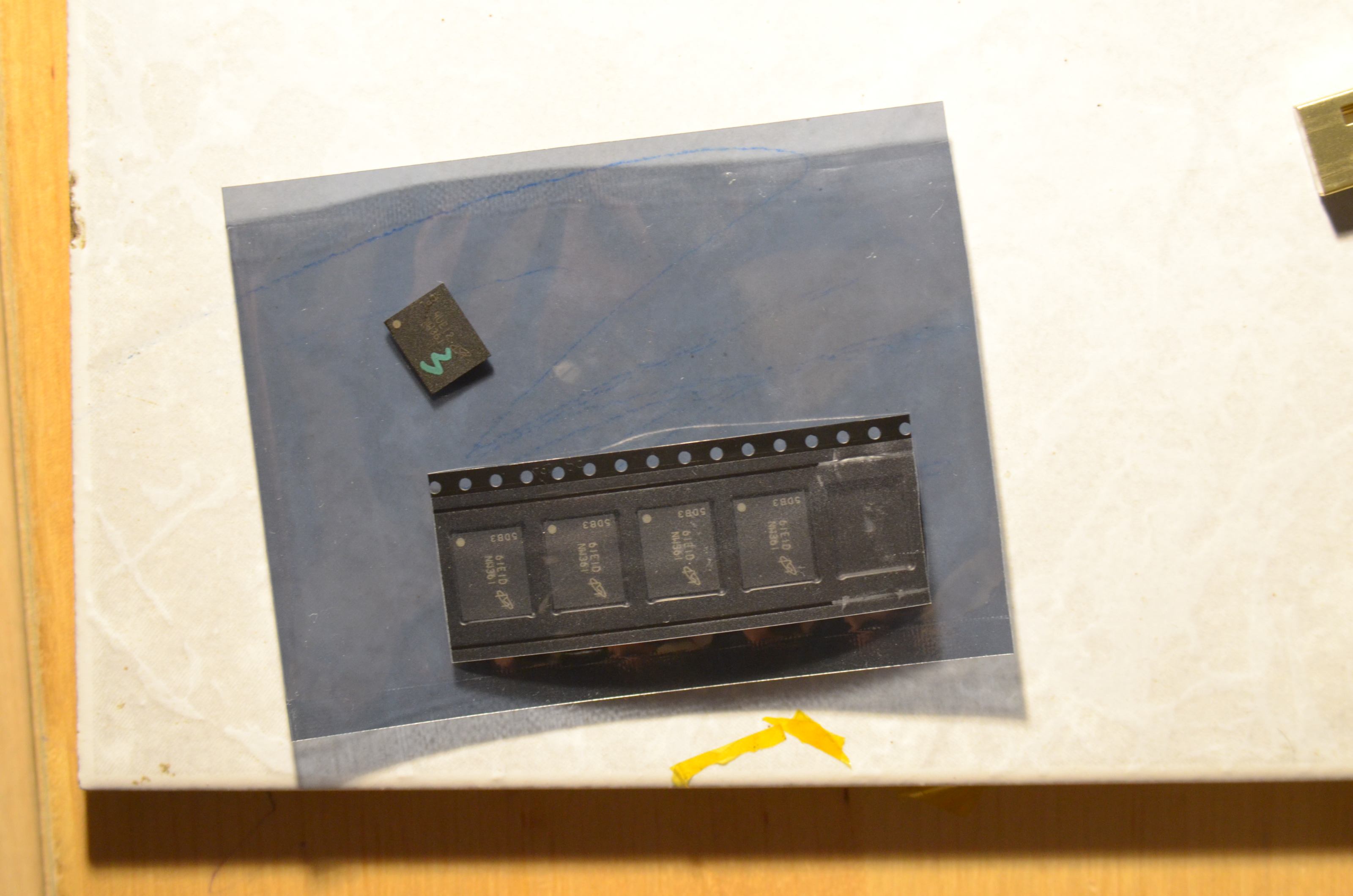
Here is the NAND chip with number "3" drawn on it:

If DM365 chip isn't printing anything, then the bootloader on NAND is damaged. I tried flashing the bootloader using instructions from here:
Flashing firmware on DaVinci media processors · mefistotelis/phantom-firmware-tools Wiki · GitHub

But I wasn't able to flash the image. Flashing was ending with message about failure to open NAND:
Code:
Waiting for SFT on the DM36x...
        Target: Starting UART Boot...
        Target: BOOTUBL
BOOTUBL commmand received. Returning CMD and command...
CMD value sent.  Waiting for DONE...
        Target:    DONE
DONE received. Command was accepted.
Sending the UBL image
Waiting for SENDIMG sequence...
        Target: NAND_open() failed!Starting UART Boot...
        Target: BOOTUBL

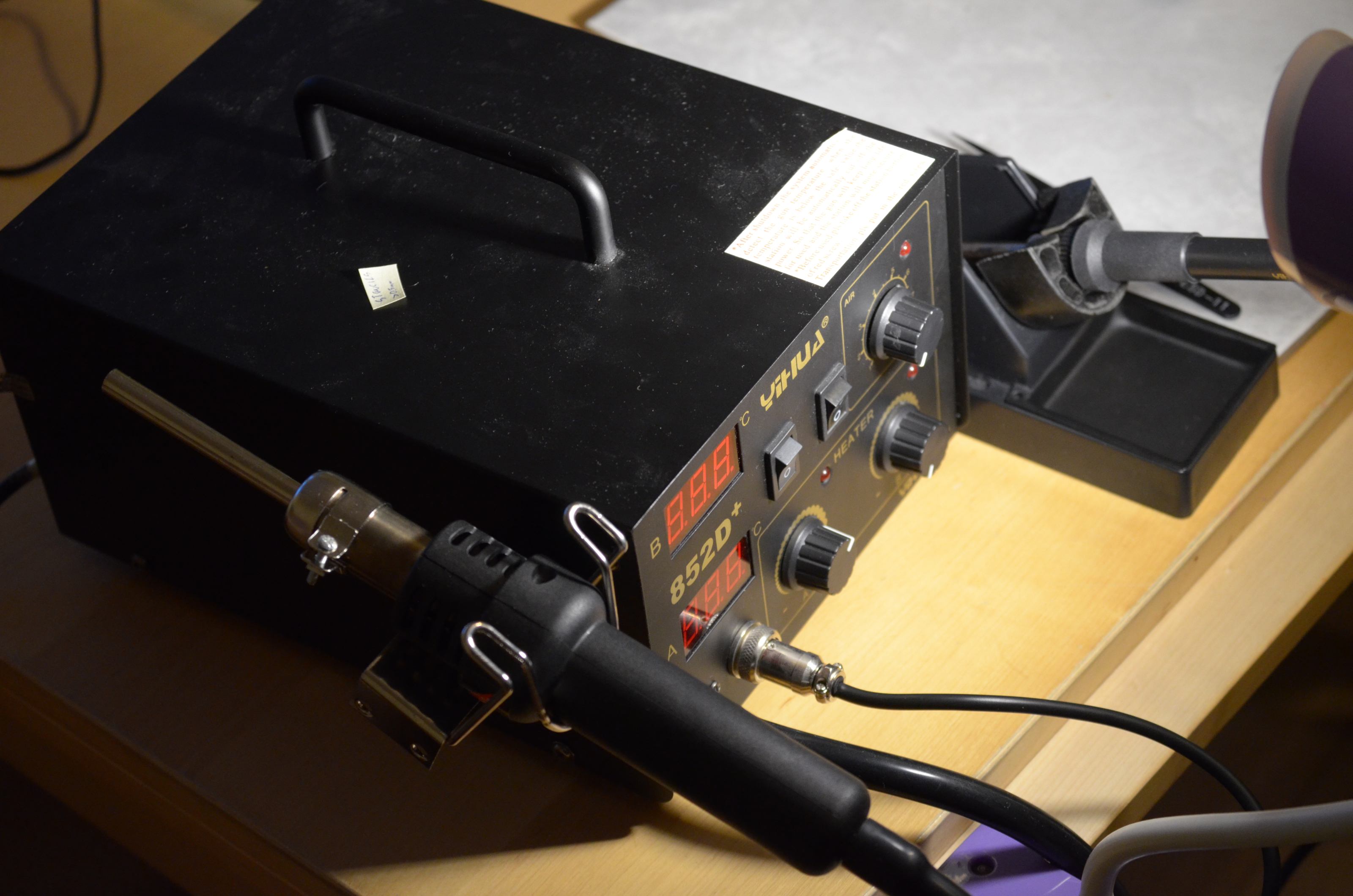
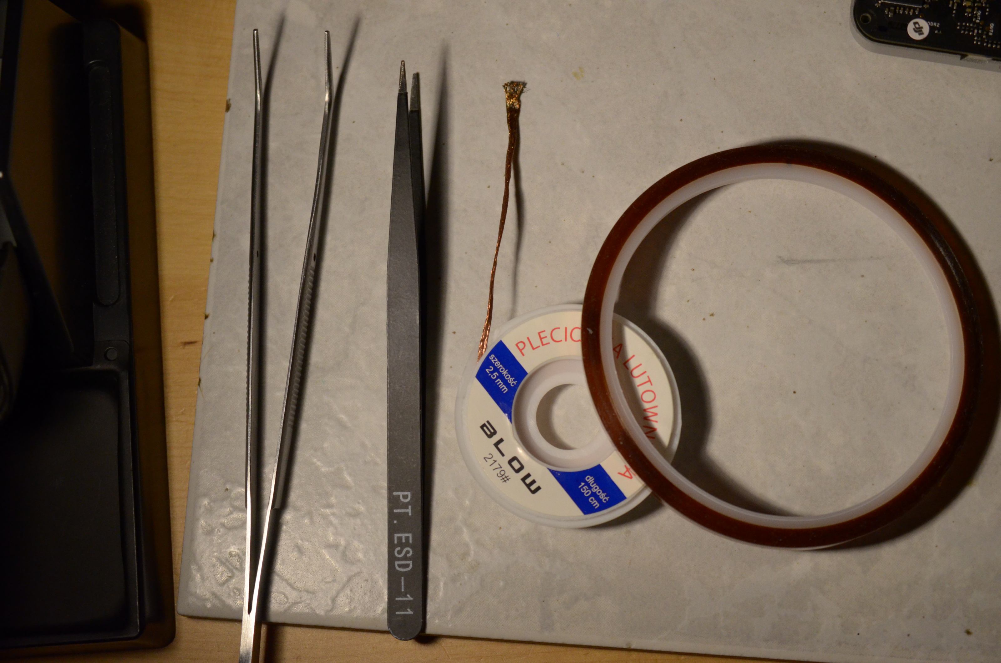
Conclusion - The NAND chip is either not touching the board correctly and needs re-flowing the solder, or is damaged and needs replacing. I gathered a cheapest BGA soldering equipment I could find:

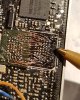
With the equipment received from China, I went to action. I used heat-resistant tape to shield the components around NAND. First I tried heating-up the NAND chip and re-flowing it, but nothing changed - still "NAND_open() failed". Then I heated it up again and gently pressed the chip, to make any smaller solder balls connect. Unfortunately, that connected too much - the chip became a short, and caused the whole FTDI to disconnect because of high current draw. I tried heating up the chip even more to make it wiggle and re-form the solder balls, but couldn't do this - the chip is so large that it won't dance under the hot air, and the ultra-cheap soldering station won't allow me to increase the air flow enoughly.

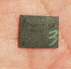
So I bought a few replacement NAND chips in China. Removed the old chip, cleaned the pads with wick, put a little soldering paste on it and soldered a new chip, placing it very carefully to the white outline of the chip visible on the board.

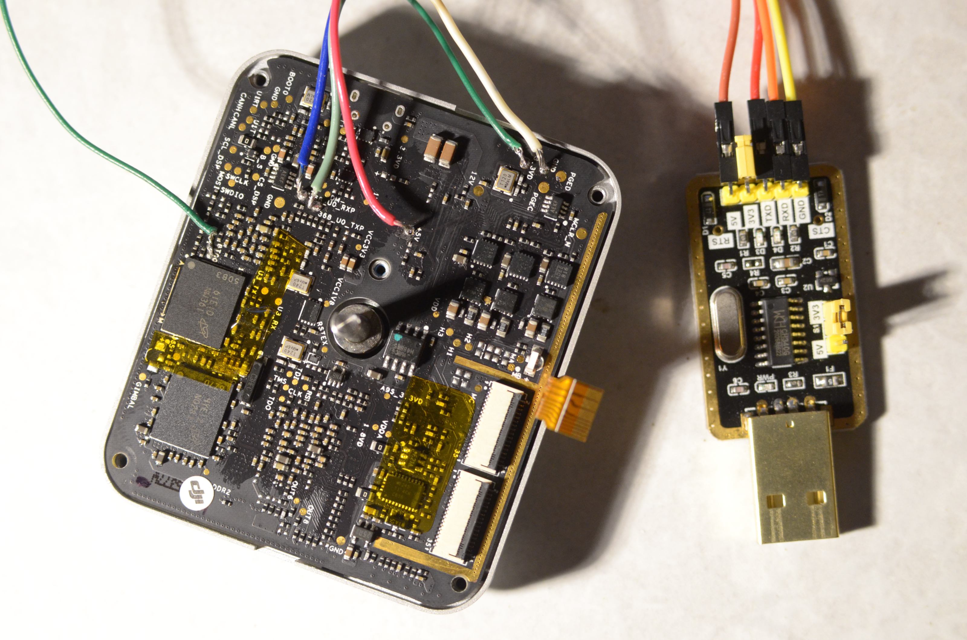
Then, when I connected it back to PC - I was able to write bootloader to the flash. It worked! I had to do several tries though, probably because of poor quality (or too long) cables. [EDIT: now I know it was not due to cables, but because my USB port couldn't deliver enough (over 700mA @5V) power] Here is my flashing configuration:

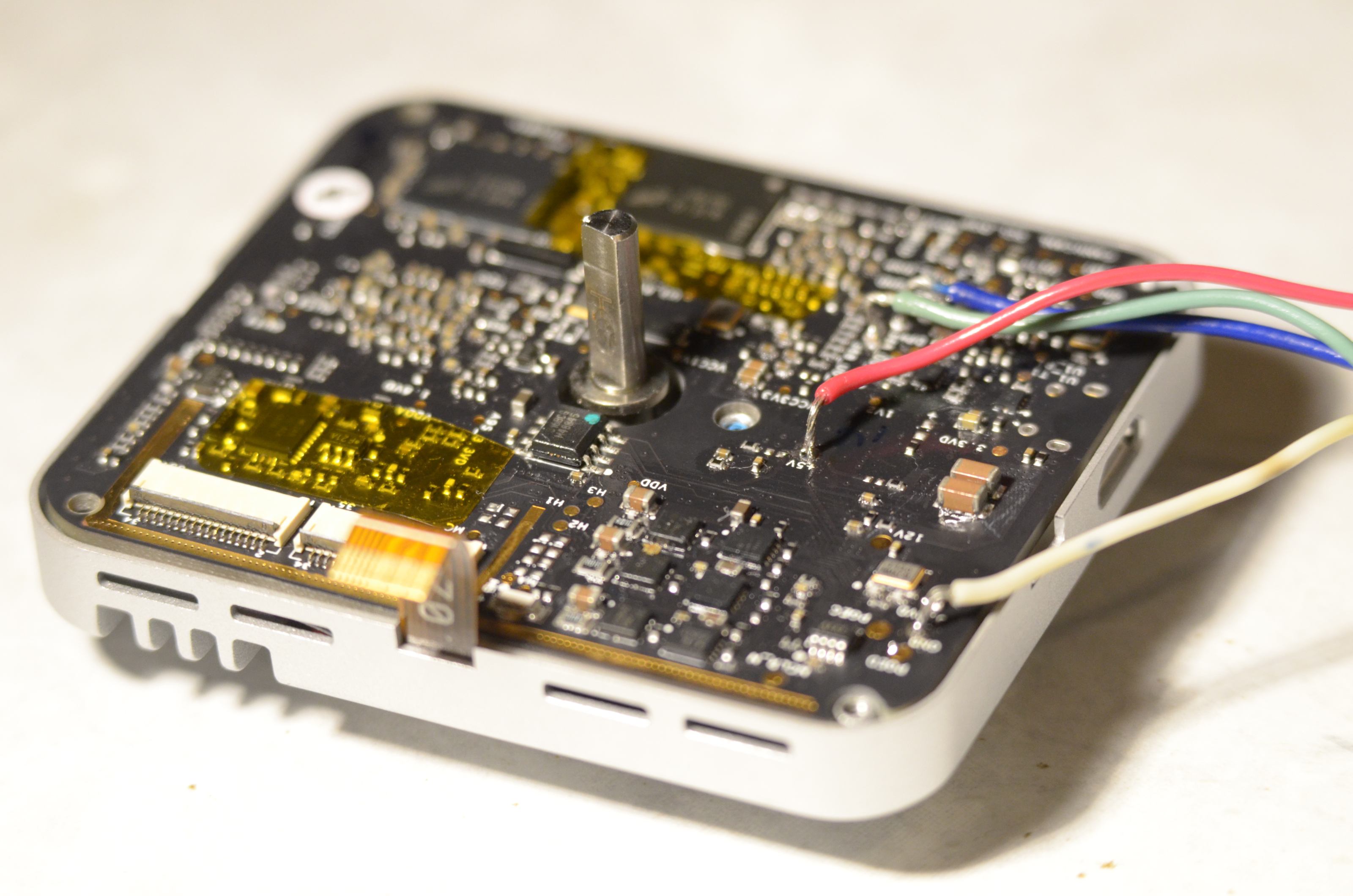
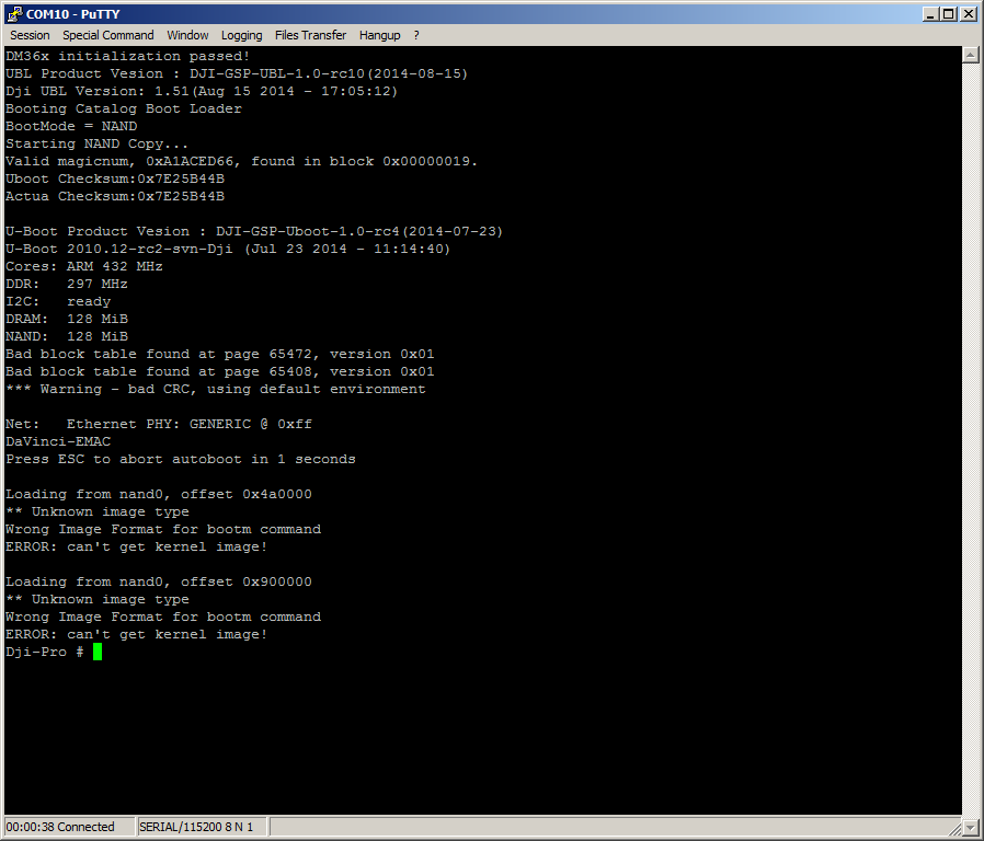
After the bootloader was flashed, I disconnected the green cable which was causing it to boot internally and spew BOOTME:

Without this cable, the chip should get back to trying to boot from NAND. I connected it back to PC to check whether bootloader works. And it does!

Now, I need a full image of a working NAND to make the rest of it work, but it's already a success.
Anyway, if anyone happens to have such image, or has FTDI connected and can download it from the board - I'll be interested in that.
20170929_163114 - copia.jpg
20171221_020630.jpg
 
  • Like
Reactions: quaddamage
hello guys,
I successfully managed to recover everything with all steps. I didn't use USB (didn't soldered cables to mainboard nor didn't use usb flash) That's why the recovery system couldn't mount /dev/sda, because it has not been recognized. I transferred everything via lrz tool and YMODEM.
Thanks a lot.
Hello dear. How did you connect to the board? I think it's the method that uses quadd. Does it work at more than 8fps? Did you upload a new name or the original one? We appreciate any data that can add. From already thank you very much. regards!
 
Hi,
received a another "dead" P3P Gimbal-Board.
Connected it with 5 V and nothing to see on U0_RX/TX.
When I apply 3.3 V to BT00/01 I receive a bootme
So I tried to load the bootloader with "sfh_DM36x -nandflash -v -p "COM9" ubl1.img u-boot.img"
But received following output:
Code:
-----------------------------------------------------
   TI Serial Flasher Host Program for DM36x
   (C) 2009, Texas Instruments, Inc.
   Ver. 1.50
-----------------------------------------------------


Flashing NAND with ubl1.img and u-boot.img.


Attempting to connect to device COM9...
Press any key to end this program at any time.


Waiting for the DM36x...
        Target:  BOOTME
BOOTME commmand received. Returning ACK and header...
ACK command sent. Waiting for BEGIN command...
        Target:   BEGIN
BEGIN commmand received. Sending CRC table...
 100% [
                           CRC table sent....


Waiting for DONE...
        Target:    DONE
DONE received.  Sending the UBL...
 100% [
                              UBL sent....


        Target:    DONE
DONE received.  UBL was accepted.
UBL transmitted successfully.


Waiting for SFT on the DM36x...
        Target: Starting UART Boot...
        Target: BOOTUBL
BOOTUBL commmand received. Returning CMD and command...
CMD value sent.  Waiting for DONE...
        Target:    DONE
DONE received. Command was accepted.
Sending the UBL image
File ubl1.img is not present.


Interfacing to the DM36x via UART failed.
Please reset or power-cycle the board and try again...

Where can I find the correct "sfh_DM36x". Did I need a special ubl1.img and u-boot.img? I used one I found in that forum for the Phantom 2.
Or is the NAND broken and replacing it will fix the problem?
Edit: Can the oscillator be the problem. Looks pretty weird.
01908392-ACDC-4029-8E27-BE3D87FDBA64.jpeg
 
  • Like
Reactions: GUCCI40
@Flightrun The issue is exactly as the message said. There is no need to search for a second bottom here.
Code:
File ubl1.img is not present.

For u-boot images version - if flashing Ph3, I would use images from Ph3.
 
Dear, I do not think it's the Chip nand, quadd. post, the message that comes out when the nand is defective in command line goes "nand open" page 1 you can see it. I get it exactly with the nand broken. Your problem for me, since I spend a lot, is that the UBL that you use is not allowed to Flash through the Texas SFH. quadd knows how to flash from linux, but if the unit does not boot for the first time I do not think there is any way, just using the SFH, with the UBL to let it load. There are several, then it can be replaced once the Linux is loaded. Quadd is a genius, I research and I have enough experience, I live this exceptional post about the DM365 and its nand corrupt or physically broken. the only problem that we still can not solve is that they remain at 8fps. but I think that perhaps together we can achieve some Greetings.
 
Your problem for me, since I spend a lot, is that the UBL that you use is not allowed to Flash through the Texas SFH.

Yeah, that might be the source of the issue. Either no permissions, the file is in invalid directory, or the working directory path is too long.

quadd knows how to flash from linux, but if the unit does not boot for the first time I do not think there is any way

Yes, it is possible to flash from the DaVinci Linux; but it's not very useful when the chip does not boot.

the only problem that we still can not solve is that they remain at 8fps. but I think that perhaps together we can achieve some Greetings.

We're on a good way to solve the 8fps issue. The issue lies with encryption key which needs to be the same on DaVinci and Ambarella. We need to write some kind of "unofficial service software" which would read an encryption key from Ambarella and exchange it with DaVinci. I asked Github guys for help with a framework for sending DUML packets to the drone.
 
Hello.
I have P3A, and top gimbal board not have DaVinchi cheap. I try repair firmware, write BIN to SD card, but it not flashing. In board flashing green led (4 try), red led (4 try), green led never ending.
I connect to U0_T U0_R via FTDI adapter and i see this:
---------------------------------------------
Cortex Boot-Up Success

Cortex freq: 504000000
ARM freq: 132000000
DDR freq: 396000000
Core freq: 216000000
iDSP freq: 264000000
AXI freq: 168000000
AHB freq: 108000000
APB freq: 54000000
UART freq: 1846153
SD0 freq: 24000000
SD1 freq: 24000000
---------------------------------------------

Start WDT timer OK.
Magic: 0x10cad81c 0x4aca100e 0x184ad006
System COLD boot.
Continue to booting up ......


---------------------------------------------
Cortex Boot-Up Success

Cortex freq: 504000000
ARM freq: 17600000
DDR freq: 396000000
Core freq: 216000000
iDSP freq: 264000000
AXI freq: 168000000
AHB freq: 108000000
APB freq: 54000000
UART freq: 1846153
SD0 freq: 54000000
SD1 freq: 24000000
---------------------------------------------

Start WDT timer OK.
Magic: 0x87651234 0x1 0x789aedca
System WARM boot.
Continue to booting up ......


---------------------------------------------
Cortex Boot-Up Success

Cortex freq: 504000000
ARM freq: 17600000
DDR freq: 396000000
Core freq: 216000000
iDSP freq: 264000000
AXI freq: 168000000
AHB freq: 108000000
APB freq: 54000000
UART freq: 1846153
SD0 freq: 30857142
SD1 freq: 24000000
---------------------------------------------

Start WDT timer OK.
Magic: 0x87651234 0x2 0x789aedc9
System WARM boot.
Continue to booting up ......


---------------------------------------------
Cortex Boot-Up Success

Cortex freq: 504000000
ARM freq: 17600000
DDR freq: 396000000
Core freq: 216000000
iDSP freq: 264000000
AXI freq: 168000000
AHB freq: 108000000
APB freq: 54000000
UART freq: 1846153
SD0 freq: 30857142
SD1 freq: 24000000
---------------------------------------------

Start WDT timer OK.
Magic: 0x87651234 0x3 0x789aedc8
System WARM boot.
Continue to booting up ......


---------------------------------------------
Cortex Boot-Up Success

Cortex freq: 504000000
ARM freq: 17600000
DDR freq: 396000000
Core freq: 216000000
iDSP freq: 264000000
AXI freq: 168000000
AHB freq: 108000000
APB freq: 54000000
UART freq: 1846153
SD0 freq: 30857142
SD1 freq: 24000000
---------------------------------------------

Start WDT timer OK.
Magic: 0x87651234 0x4 0x789aedcf
System WARM boot.
Detecting done ......

[00000000][CA9_0] [DJI] Start WDT of 20 seconds for boot up......

[00000000][CA9_0] [Version 1.0.11824], Oct 16 2015, 14:06:46


[00000000][CA9_0] [DJI] SD Updater Version [v01.25.5432] Build Sep 23 2016 17:03:19


[00000329][CA9_0] [DJI] Stop WDT.

[00000329][CA9_0] [DJI] Firmware updating......

[00000329][CA9_0] Card In Slot.
[00000630][CA9_0] SD clock source, frequency = 216000000
[00000630][CA9_0] SDCalcClk for SD card initiation:: Actual Clk = 140625, pCLK = 128
[00000650][CA9_0] start to check media
[00000654][CA9_0] AmbaSD_InitCard - SD_CARD OK
[00000659][CA9_0] [DjiSDInit]Unsupported SD FS, current forma4
---------------------------------------------
Cortex Boot-Up Success

Cortex freq: 504000000
ARM freq: 17600000
DDR freq: 396000000
Core freq: 216000000
iDSP freq: 264000000
AXI freq: 168000000
AHB freq: 108000000
APB freq: 54000000
UART freq: 1846153
SD0 freq: 43200000
SD1 freq: 24000000
---------------------------------------------

Start WDT timer OK.
Magic: 0x87651234 0x5 0x789aedce
System WARM boot.
Detecting done ......

[00000000][CA9_0] [DJI] Start WDT of 20 seconds for boot up......

[00000000][CA9_0] [Version 1.0.11824], Oct 16 2015, 14:06:46


[00000000][CA9_0] [DJI] SD Updater Version [v01.25.5432] Build Sep 23 2016 17:03:19


[00000329][CA9_0] [DJI] Stop WDT.

[00000329][CA9_0] [DJI] Firmware updating......

[00000329][CA9_0] Card In Slot.
[00000630][CA9_0] SD clock source, frequency = 216000000
[00000630][CA9_0] SDCalcClk for SD card initiation:: Actual Clk = 140625, pCLK = 128
[00000650][CA9_0] start to check media
[00000654][CA9_0] AmbaSD_InitCard - SD_CARD OK
[00000659][CA9_0] [DjiSDInit]Unsupported SD FS, current forma
---------------------------------------------
Cortex Boot-Up Success

Cortex freq: 504000000
ARM freq: 17600000
DDR freq: 396000000
Core freq: 216000000
iDSP freq: 264000000
AXI freq: 168000000
AHB freq: 108000000
APB freq: 54000000
UART freq: 1846153
SD0 freq: 43200000
SD1 freq: 24000000
---------------------------------------------

Start WDT timer OK.
Magic: 0x87651234 0x6 0x789aedcd
System WARM boot.
Detecting done ......

[00000000][CA9_0] [DJI] Start WDT of 20 seconds for boot up......

[00000000][CA9_0] [Version 1.0.11824], Oct 16 2015, 14:06:46


[00000000][CA9_0] [DJI] SD Updater Version [v01.25.5432] Build Sep 23 2016 17:03:19


[00000329][CA9_0] [DJI] Stop WDT.

[00000329][CA9_0] [DJI] Firmware updating......

[00000329][CA9_0] Card In Slot.
[00000630][CA9_0] SD clock source, frequency = 216000000
[00000630][CA9_0] SDCalcClk for SD card initiation:: Actual Clk = 140625, pCLK = 128
[00000650][CA9_0] start to check media
[00000654][CA9_0] AmbaSD_InitCard - SD_CARD OK
[00000659][CA9_0] [DjiSDInit]Unsupported SD FS, current forma
---------------------------------------------
Cortex Boot-Up Success

Cortex freq: 504000000
ARM freq: 17600000
DDR freq: 396000000
Core freq: 216000000
iDSP freq: 264000000
AXI freq: 168000000
AHB freq: 108000000
APB freq: 54000000
UART freq: 1846153
SD0 freq: 43200000
SD1 freq: 24000000
---------------------------------------------

Start WDT timer OK.
Magic: 0x87651234 0x7 0x789aedcc
System WARM boot.
Detecting done ......

[00000000][CA9_0] [DJI] Start WDT of 20 seconds for boot up......

[00000000][CA9_0] [Version 1.0.11824], Oct 16 2015, 14:06:46


[00000000][CA9_0] [DJI] SD Updater Version [v01.25.5432] Build Sep 23 2016 17:03:19


[00000329][CA9_0] [DJI] Stop WDT.

[00000329][CA9_0] [DJI] Firmware updating......

[00000329][CA9_0] Card In Slot.
[00000630][CA9_0] SD clock source, frequency = 216000000
[00000630][CA9_0] SDCalcClk for SD card initiation:: Actual Clk = 140625, pCLK = 128
[00000650][CA9_0] start to check media
[00000654][CA9_0] AmbaSD_InitCard - SD_CARD OK
[00000659][CA9_0] [DjiSDInit]Unsupported SD FS, current forma
---------------------------------------------
Cortex Boot-Up Success

Cortex freq: 504000000
ARM freq: 17600000
DDR freq: 396000000
Core freq: 216000000
iDSP freq: 264000000
AXI freq: 168000000
AHB freq: 108000000
APB freq: 54000000
UART freq: 1846153
SD0 freq: 43200000
SD1 freq: 24000000
---------------------------------------------

Start WDT timer OK.
Magic: 0x87651234 0x8 0x789aedc3
System WARM boot.
Detecting done ......

[00000000][CA9_0] [DJI] Start WDT of 20 seconds for boot up......

[00000000][CA9_0] [Version 1.0.11824], Oct 16 2015, 14:06:46


[00000000][CA9_0] [DJI] SD Updater Version [v01.25.5432] Build Sep 23 2016 17:03:19


[00000329][CA9_0] [DJI] Stop WDT.

[00000329][CA9_0] [DJI] Firmware updating......

[00000329][CA9_0] Card In Slot.
[00000630][CA9_0] SD clock source, frequency = 216000000
[00000630][CA9_0] SDCalcClk for SD card initiation:: Actual Clk = 140625, pCLK = 128
[00000650][CA9_0] start to check media
[00000654][CA9_0] AmbaSD_InitCard - SD_CARD OK
[00000659][CA9_0] [DjiSDInit]Unsupported SD FS, current forma
---------------------------------------------
Cortex Boot-Up Success

Cortex freq: 504000000
ARM freq: 17600000
DDR freq: 396000000
Core freq: 216000000
iDSP freq: 264000000
AXI freq: 168000000
AHB freq: 108000000
APB freq: 54000000
UART freq: 1846153
SD0 freq: 43200000
SD1 freq: 24000000
---------------------------------------------

Start WDT timer OK.
Magic: 0x87651234 0x9 0x789aedc2
System WARM boot.
Detecting done ......

[00000000][CA9_0] [DJI] Start WDT of 20 seconds for boot up......

[00000000][CA9_0] [Version 1.0.11824], Oct 16 2015, 14:06:46


[00000000][CA9_0] [DJI] SD Updater Version [v01.25.5432] Build Sep 23 2016 17:03:19


[00000329][CA9_0] [DJI] Stop WDT.

[00000329][CA9_0] [DJI] Firmware updating......

[00000329][CA9_0] Card In Slot.
[00000630][CA9_0] SD clock source, frequency = 216000000
[00000630][CA9_0] SDCalcClk for SD card initiation:: Actual Clk = 140625, pCLK = 128
[00000650][CA9_0] start to check media
[00000654][CA9_0] AmbaSD_InitCard - SD_CARD OK
[00000659][CA9_0] [DjiSDInit]Unsupported SD FS, current forma4
---------------------------------------------
Cortex Boot-Up Success

Cortex freq: 504000000
ARM freq: 17600000
DDR freq: 396000000
Core freq: 216000000
iDSP freq: 264000000
AXI freq: 168000000
AHB freq: 108000000
APB freq: 54000000
UART freq: 1846153
SD0 freq: 43200000
SD1 freq: 24000000
---------------------------------------------

Start WDT timer OK.
Magic: 0x87651234 0xa 0x789aedc1
System WARM boot.
Rolling Back done ......


---------------------------------------------
Cortex Boot-Up Success

Cortex freq: 504000000
ARM freq: 17600000
DDR freq: 396000000
Core freq: 216000000
iDSP freq: 264000000
AXI freq: 168000000
AHB freq: 108000000
APB freq: 54000000
UART freq: 1846153
SD0 freq: 30857142
SD1 freq: 24000000
---------------------------------------------

Start WDT timer OK.
Magic: 0x87651234 0xb 0x789aedc0
System WARM boot.
Rolling Back done ......


------------------------
..............
What format SD card need for Ambarella, for reflash STM32 MC?
 
  • Like
Reactions: GUCCI40

Recent Posts

Members online

Forum statistics

Threads
143,094
Messages
1,467,600
Members
104,980
Latest member
ozmtl