One last follow up: for the serial connection, I should be on the 368_u0_tx/rx pins correct?
Yes. The output you shared suggests you're on correct pins, and transmission parameters are correct.


One last follow up: for the serial connection, I should be on the 368_u0_tx/rx pins correct?
Looks like Ambarella dead or Ambarella NAND. No output because Advanced board doesn't have DaVinci chip.Great to hear about your success quaddamage!
I have another board Im messing with now. Its from a P3 advanced. Its not outputting anything even with the bootpins to 3.3V. No light in the LED either. Its consuming 600mA on 5V.
Any suggestions? or is this board simply dead?
Looks like Ambarella dead or Ambarella NAND.
No output because Advanced board doesn't have DaVinci chip.

Here is the NAND chip with number "3" drawn on it:
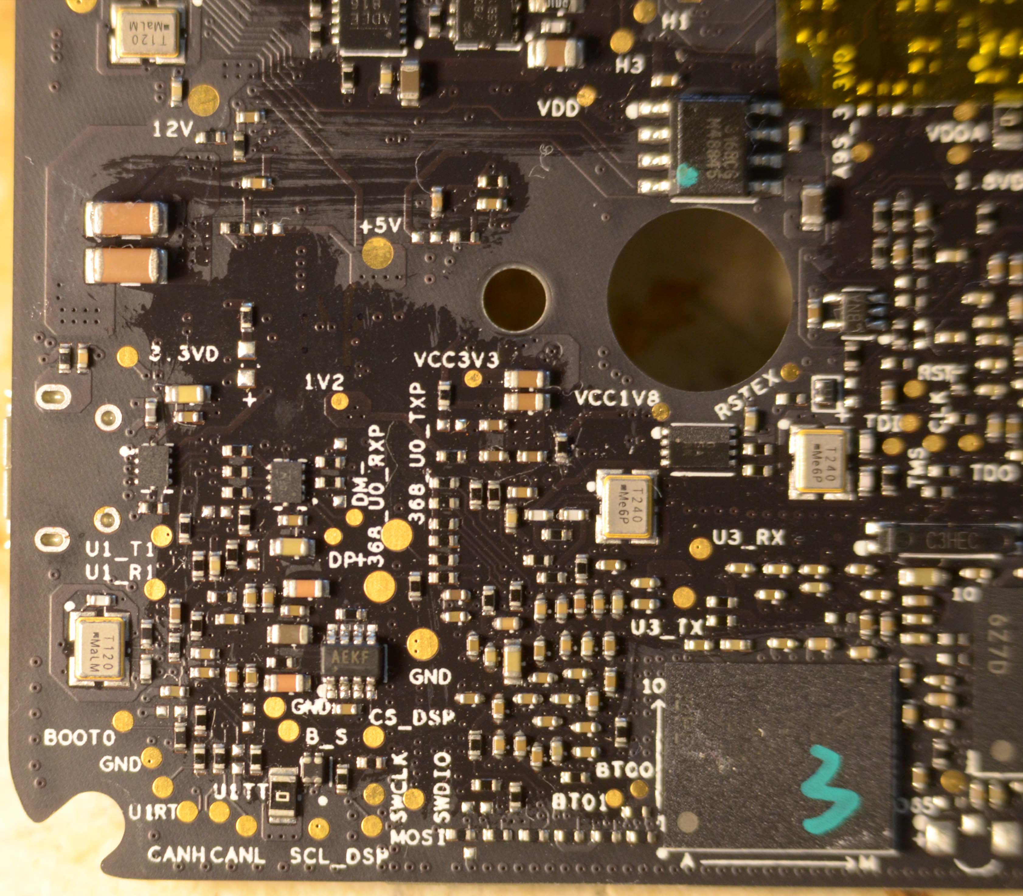
Ph3_pro_gimbal_board_before
Phantom 3 Pro gimbal board with dm365 NAND chip "3" visible.
So I bought a few replacement NAND chips in China. Removed the old chip, cleaned the pads with wick, put a little soldering paste on it and soldered a new chip, placing it very carefully to the white outline of the chip visible on the board.
Hi, What is the Nand chip part # for replacements?
GUCCI40 said:Could you post more detailed part of the commands to record a new chip? I can load the ubl and ubot, the chip starts Ok, but I can not load the UBI part, it is not very clear in the wiki explanation, I manage serial well by Uart but I do not understand well enter by usb, I would appreciate it very much if you can put a scheme or details of the commands to load all the files exactly so that it starts the whole system
Code:root@Dji-Pro:/tmp# mount /dev/sda sdcard [ 60.090000] [EXFAT] trying to mount... mount: mounting /dev/sda on sdcard failed: Input/output error
dmesg | tail -n 20My latest research that may interest you is the current failure in many Gimbal of PH4 Pro and Adv, if you use any of these data, I will gladly send my humble experience in repairing them without changing parts, detect failure in construction of gimbal engines that fail prematurely.
I had all the files in root folder at the same time. There is no need for copying them one by one.the SD is in the reader with the UBI file of 23 mb in the root directory of the SD as I did with the other files, I did it one by one deleting the previous one. the Wiki indicates doing it one by one. Or do you send the entire set in the DJI folder in one go?
I upload some photos of me about this experience to complement your excellent post. It is very easy in this model that nand Chip, is broken crush crack by the pressure exerted by the arm of the camera when it is forced in a fall to the floor, the crack in the chip is almost imperceptible to the eye, obviously this does not happen ne the ADV or 4k version and what do they use the dm365 with their nand flash.Here is a success story I wanted to share.
I had a Phantom 3 Pro gimbal which didn't allowed me to see the FPV feed. Photos and movies were recorded on sd-card, there was just no live video - only grey background - in Dji Go.
By connecting another gimbal, I narrowed down the problem to gimbal itself - a different gimbal (which had the same firmware installed) worked fine.
Then I disassembled the gimbal. I looked at available information about the board:
WM320 Gimbal top board · mefistotelis/phantom-firmware-tools Wiki · GitHub
On the schematic, video feed is encoded by media processor model DM365:
dji-hardware-schematics/phantom_3_pro_overview.pdf at master · mefistotelis/dji-hardware-schematics · GitHub
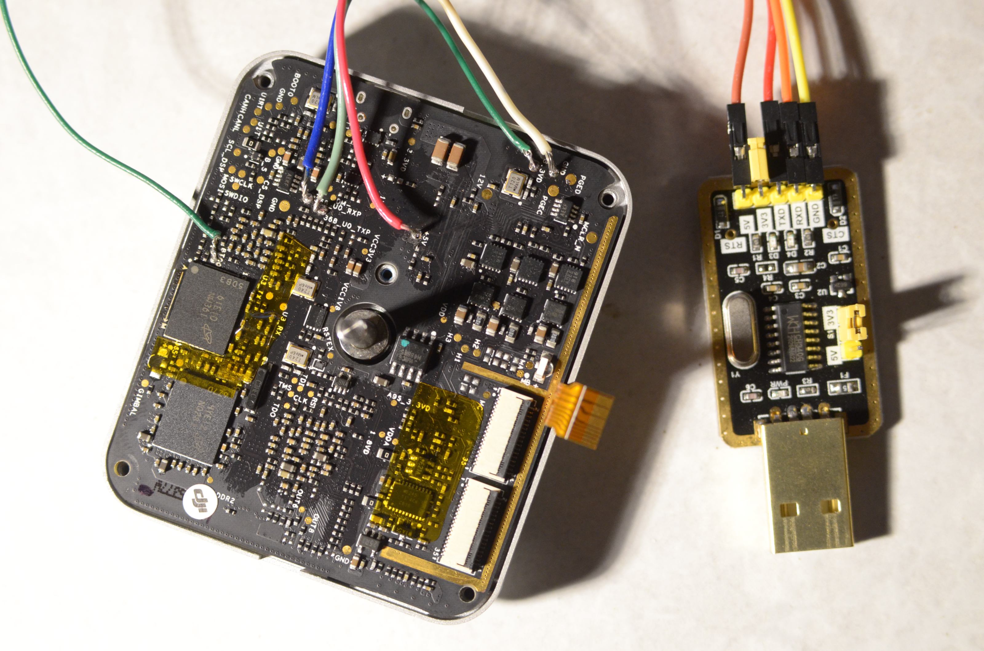
To check whether the media processor is working correctly, I tapped to UART interface of the DM365 chip with TTL-to-USB converter (aka FTDI). See here for details:
Firmware m0800 · mefistotelis/phantom-firmware-tools Wiki · GitHub
I opened PuTTY on the interface before connecting 5V power for the board, then connected the power. There was no output on the console while the board was booting. But the board was booting - I was able to see the diode blinking on it. Which means either my FTDI configuration was bad, or the chip just wasn't producing any output.
To check which is true (and also fix the issue if this turns out to be a chip boot issue), I shorted the boot pins to 3.3V and connected the board to PC again. This should cause the DM365 chip to boot internally, without use of NAND. This time I was able to see a series of "BOOTME BOOTME BOOTME" messages. This ment my FTDI configuration is fine, the DM365 chip really wasn't printing anything when trying to boot from NAND.
Here is the NAND chip with number "3" drawn on it:
Ph3_pro_gimbal_board_before
Phantom 3 Pro gimbal board with dm365 NAND chip "3" visible.
If DM365 chip isn't printing anything, then the bootloader on NAND is damaged. I tried flashing the bootloader using instructions from here:
Flashing firmware on DaVinci media processors · mefistotelis/phantom-firmware-tools Wiki · GitHub
But I wasn't able to flash the image. Flashing was ending with message about failure to open NAND:
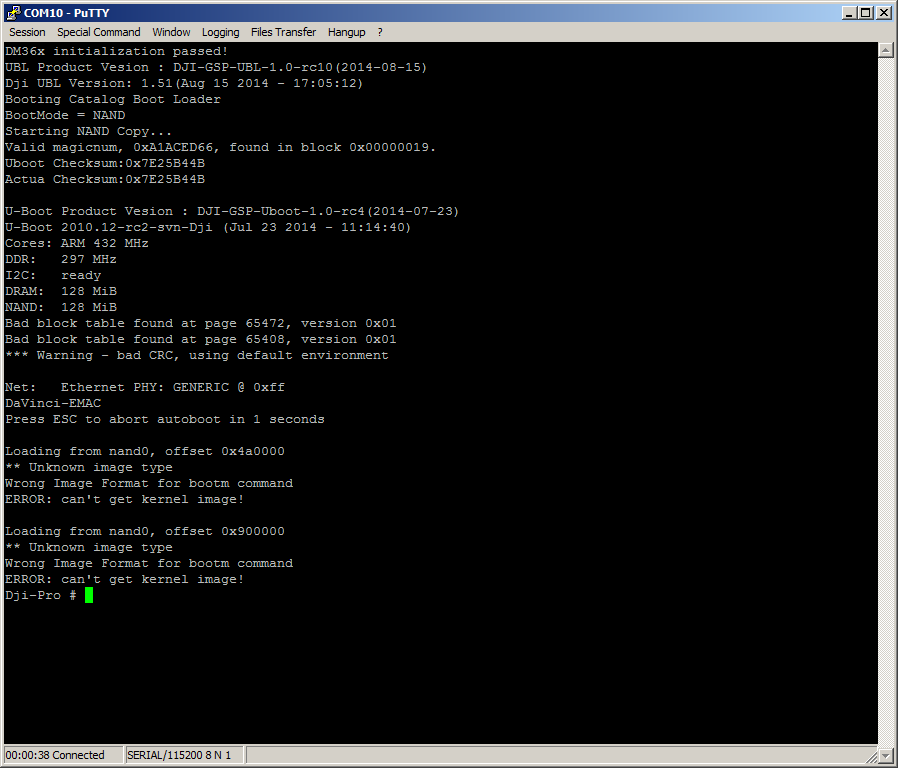
Code:Waiting for SFT on the DM36x... Target: Starting UART Boot... Target: BOOTUBL BOOTUBL commmand received. Returning CMD and command... CMD value sent. Waiting for DONE... Target: DONE DONE received. Command was accepted. Sending the UBL image Waiting for SENDIMG sequence... Target: NAND_open() failed!Starting UART Boot... Target: BOOTUBL
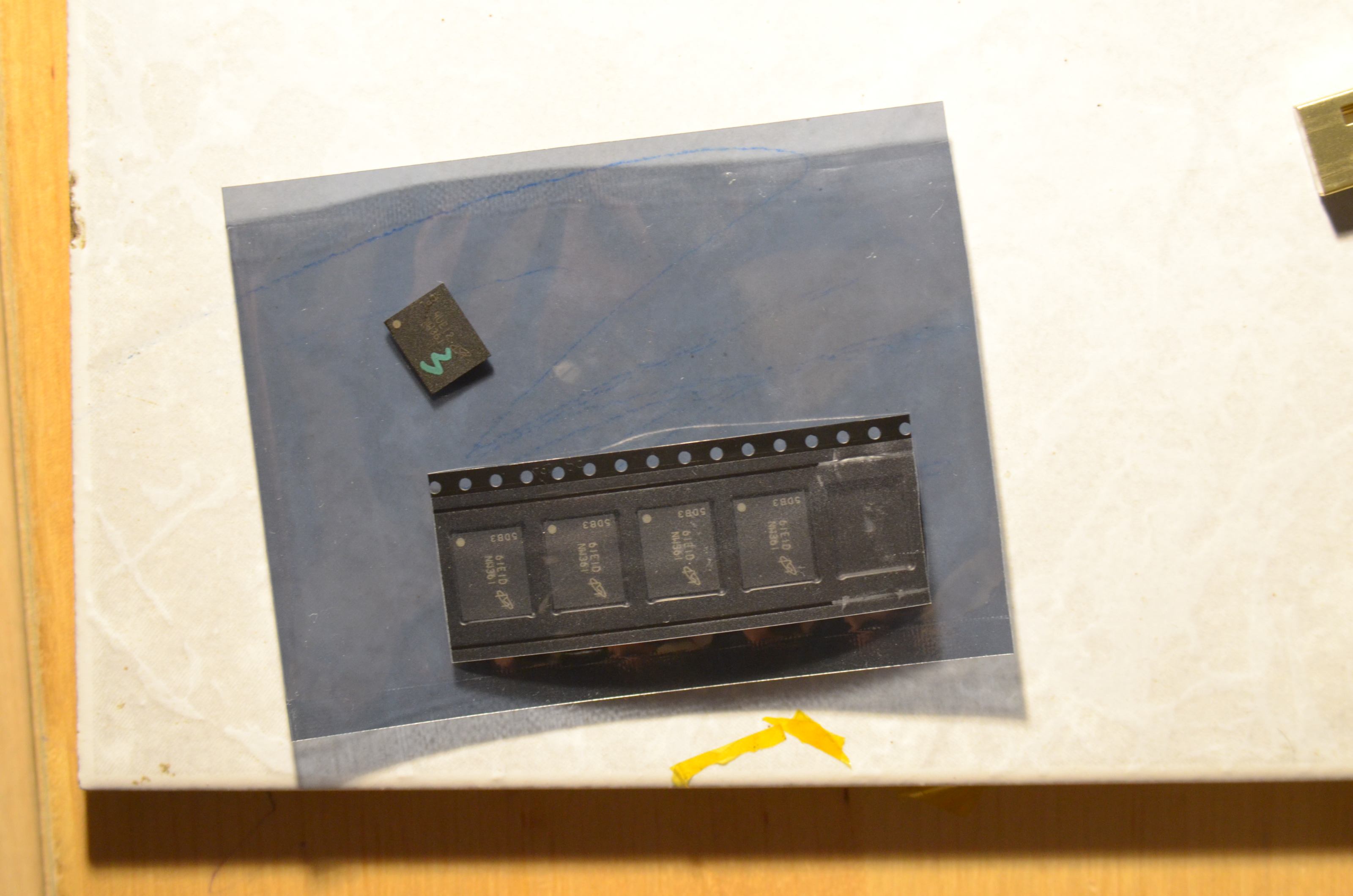
Conclusion - The NAND chip is either not touching the board correctly and needs re-flowing the solder, or is damaged and needs replacing. I gathered a cheapest BGA soldering equipment I could find:
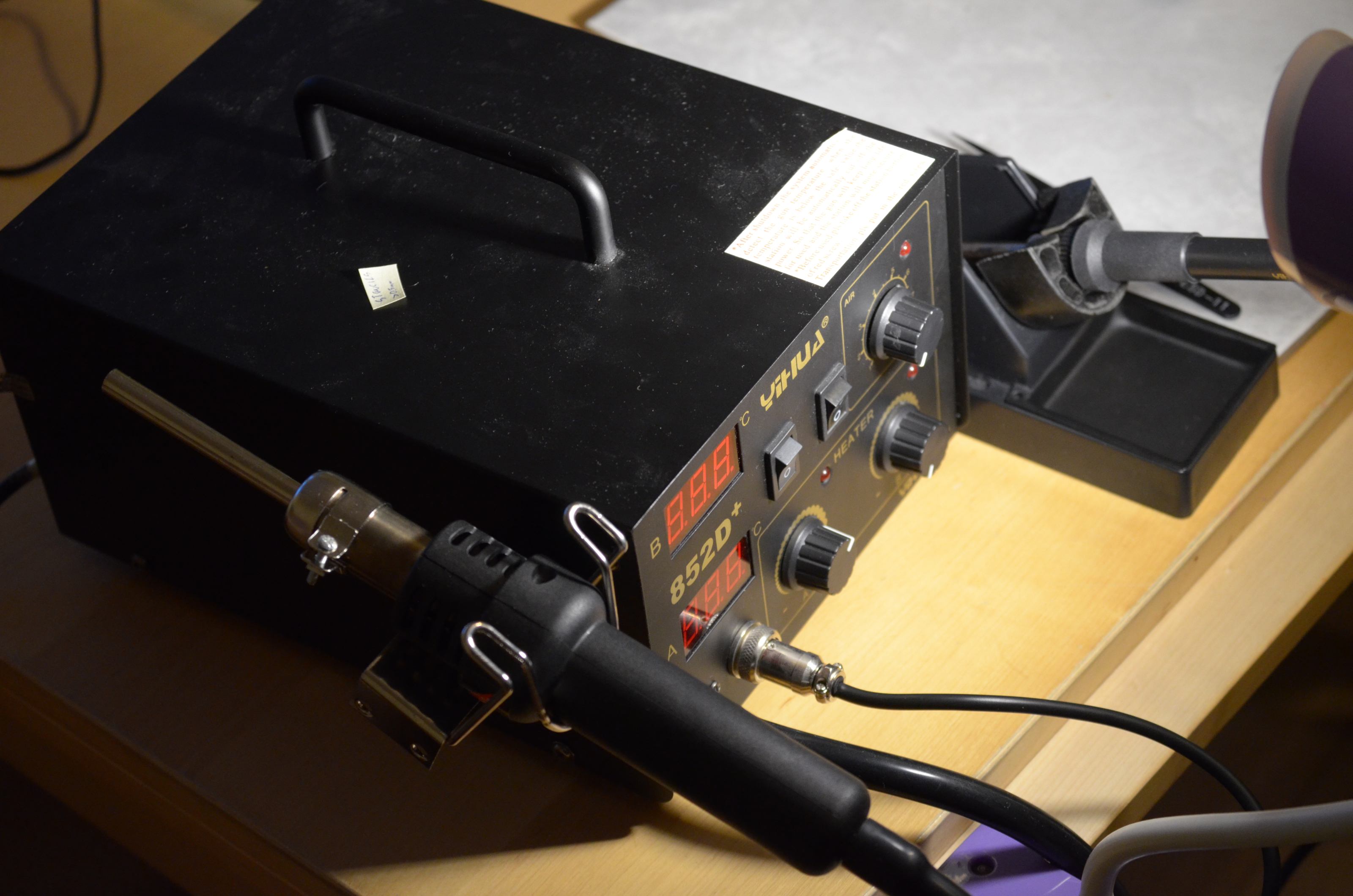
With the equipment received from China, I went to action. I used heat-resistant tape to shield the components around NAND. First I tried heating-up the NAND chip and re-flowing it, but nothing changed - still "NAND_open() failed". Then I heated it up again and gently pressed the chip, to make any smaller solder balls connect. Unfortunately, that connected too much - the chip became a short, and caused the whole FTDI to disconnect because of high current draw. I tried heating up the chip even more to make it wiggle and re-form the solder balls, but couldn't do this - the chip is so large that it won't dance under the hot air, and the ultra-cheap soldering station won't allow me to increase the air flow enoughly.
So I bought a few replacement NAND chips in China. Removed the old chip, cleaned the pads with wick, put a little soldering paste on it and soldered a new chip, placing it very carefully to the white outline of the chip visible on the board.
Then, when I connected it back to PC - I was able to write bootloader to the flash. It worked! I had to do several tries though, probably because of poor quality (or too long) cables. [EDIT: now I know it was not due to cables, but because my USB port couldn't deliver enough (over 700mA @5V) power] Here is my flashing configuration:
Dm365_fix_phase1
DM365 UART connection, including boot pads shorted to allow writing bootloader
After the bootloader was flashed, I disconnected the green cable which was causing it to boot internally and spew BOOTME:
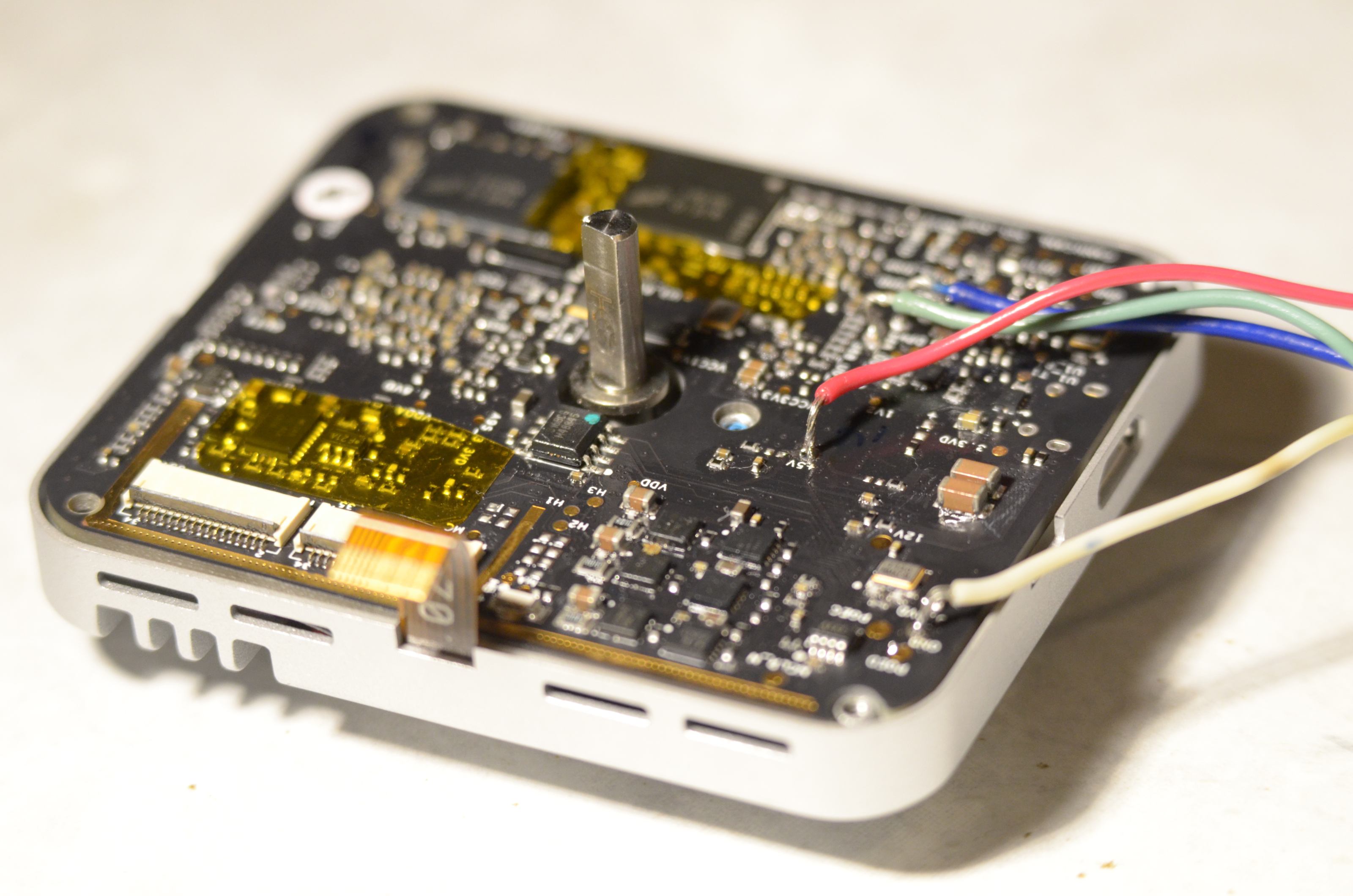
Without this cable, the chip should get back to trying to boot from NAND. I connected it back to PC to check whether bootloader works. And it does!
Now, I need a full image of a working NAND to make the rest of it work, but it's already a success.
Anyway, if anyone happens to have such image, or has FTDI connected and can download it from the board - I'll be interested in that.
ÎÈÏñ¼ü<ïéÇ¿? ÖйúÉîÛÚÕÒ´ó½®!...====== start from loader ====== ..= 55aa55aa !..app exist !..I also have a board from a P3A. Voltage seems okay on ever TP, but no LED or Video or gimbal-movement.
So I tried to connect to U0_T and U0_R but I didn‘t see anything on the output. Is this okay or is the Ambarella dead?[/CODE]
Because on U1_T1 and U1_R1 I get just “repeating garbage” or is it encrypted? And on U1RT and U1TT I get some output
Code:ÎÈÏñ¼ü<ïéÇ¿? ÖйúÉîÛÚÕÒ´ó½®!...====== start from loader ====== ..= 55aa55aa !..app exist !..
ÎÈÏñ¼ü<ïéÇ¿? ÖйúÉîÛÚÕÒ´ó½®!...====== start from loader ====== ..= 55aa55aa !. ====== Enter Loader wait data to upgrade devive ======I checked your capture_text.txt. While it clearly shows packets are sent, the format doesn't match DUML structure which the drone uses internally. It is possible that different format is used for that interface, but it is far more likely that the transmission parameters are just not right. Try finding parameters which make each packet start with 0x55.The funny thing about the garbage-log: I tried different baud-rates and bit-length. 57600 and 7-bit gives the best result.
Another funny thing: When I short U1_T1 with U1_R1 I get another output.Code:ÎÈÏñ¼ü<ïéÇ¿? ÖйúÉîÛÚÕÒ´ó½®!...====== start from loader ====== ..= 55aa55aa !. ====== Enter Loader wait data to upgrade devive ======
Step 3. Send dm365_secret.bin, Achievement Load OK OK.
Step 4. Send dm365_recovery_rootfs.bin Achievement Load OK.
Step 5. I follow the steps and commands of the WiKi Linux console start OK
to load the dm365_root_ubifs.ubi and "in this step the error occurs to me".
I checked your capture_text.txt. While it clearly shows packets are sent, the format doesn't match DUML structure which the drone uses internally. It is possible that different format is used for that interface, but it is far more likely that the transmission parameters are just not right. Try finding parameters which make each packet start with 0x55.
Ok friend, I see that we are in the same, I know a lot of the electronic part but little linux, I follow the steps of the wiki and I stay in the ubi file part. input output error, I understand that you load all in one, I do one by one as the wiki says, the quaddamage friend, has a successful experience in this, I will thank you as they package everything in a single operation or if the UBI to do it apart what commands they would use and where I place the folders in windows is good to help each other, much greetings,


We use essential cookies to make this site work, and optional cookies to enhance your experience.
