- Joined
- Nov 17, 2020
- Messages
- 4
- Reaction score
- 0
- Age
- 30
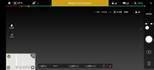
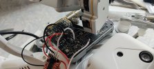
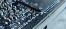
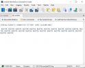
Can you help me with what to do after this point?UBL Product Vesion : DJI-GSP-UBL-1.0-rc10(2014-08-15)
Dji UBL Version: 1.51(Aug 15 2014 - 17:05:12)
Booting Catalog Boot Loader
BootMode = NAND
Starting NAND Copy...
Valid magicnum, 0xA1ACED66, found in block 0x00000019.
Uboot Checksum:0x7E25B44B
Actua Checksum:0x7E25B44B
U-Boot Product Vesion : DJI-GSP-Uboot-1.0-rc4(2014-07-23)
U-Boot 2010.12-rc2-svn-Dji (Jul 23 2014 - 11:14:40)
Cores: ARM 432 MHz
DDR: 297 MHz
I2C: ready
DRAM: 128 MiB
NAND: 128 MiB
Bad block table found at page 65472, version 0x01
Bad block table found at page 65408, version 0x01
*** Warning - bad CRC, using default environment
Net: Ethernet PHY: GENERIC @ 0xff
DaVinci-EMAC
Press ESC to abort autoboot in 1 seconds
Loading from nand0, offset 0x4a0000
** Unknown image type
Wrong Image Format for bootm command
ERROR: can't get kernel image!
Loading from nand0, offset 0x900000
Image Name: Linux-2.6.32.17-davinci1
Created: 2015-03-30 9:54:39 UTC
Image Type: ARM Linux Kernel Image (uncompressed)
Data Size: 4032832 Bytes = 3.8 MiB
Load Address: 80008000
Entry Point: 80008000
## Booting kernel from Legacy Image at 80700000 ...
Image Name: Linux-2.6.32.17-davinci1
Created: 2015-03-30 9:54:39 UTC
Image Type: ARM Linux Kernel Image (uncompressed)
Data Size: 4032832 Bytes = 3.8 MiB
Load Address: 80008000
Entry Point: 80008000
Loading Kernel Image ... OK
OK
Starting kernel ...
[ 0.000000] Kernel Product Vesion : DJI-NOHDMI-WM610-Kernel-1.0-rc6(2015-03-3 0)
[ 0.000000] Linux version 2.6.32.17-davinci1 (root@dji) (gcc version 4.3.3 (S ourcery G++ Lite 2009q1-203) ) #16 PREEMPT Mon Mar 30 17:54:38 HKT 2015
[ 0.000000] CPU: ARM926EJ-S [41069265] revision 5 (ARMv5TEJ), cr=00053177
[ 0.000000] CPU: VIVT data cache, VIVT instruction cache
[ 0.000000] Machine: DaVinci DM36x EVM
[ 0.000000] Memory policy: ECC disabled, Data cache writeback
[ 0.000000] DaVinci dm36x_rev1.2 variant 0x8
[ 0.000000] Built 1 zonelists in Zone order, mobility grouping off. Total pa ges: 12192
[ 0.000000] Kernel command line: console=ttyS0,115200n8 rw dm365_imp.oper_mod e=0 video=davincifb:vid0=0,10K:vid1=0,10Ksd0=1920x1080X16,8100K mem=48MB davin ci_enc_mngr.ch0_output=COMPOSITE davinci_enc_mngr.ch0_mode=pal ubi.mtd=2,2048 ro ot=ubi0:rootfs rootfstype=ubifs ip=off lpj=1077248
[ 0.000000] PID hash table entries: 256 (order: -2, 1024 bytes)
[ 0.000000] Dentry cache hash table entries: 8192 (order: 3, 32768 bytes)
[ 0.000000] Inode-cache hash table entries: 4096 (order: 2, 16384 bytes)
[ 0.000000] Memory: 48MB = 48MB total
[ 0.000000] Memory: 44452KB available (3640K code, 451K data, 116K init, 0K h ighmem)
[ 0.000000] SLUB: Genslabs=11, HWalign=32, Order=0-3, MinObjects=0, CPUs=1, N odes=1
[ 0.000000] Hierarchical RCU implementation.
[ 0.000000] NR_IRQS:245
[ 0.000000] Console: colour dummy device 80x30
[ 0.000000] Calibrating delay loop (skipped) preset value.. 215.44 BogoMIPS ( lpj=1077248)
[ 0.000000] Mount-cache hash table entries: 512
[ 0.000000] CPU: Testing write buffer coherency: ok
[ 0.000000] DaVinci: 8 gpio irqs
[ 0.000000] NET: Registered protocol family 16
[ 0.110000] bio: create slab <bio-0> at 0
[ 0.110000] DM365 IPIPE initialized in Continuous mode
[ 0.110000] SCSI subsystem initialized
[ 0.120000] usbcore: registered new interface driver usbfs
[ 0.120000] usbcore: registered new interface driver hub
[ 0.120000] usbcore: registered new device driver usb
[ 0.120000] vpss vpss: dm365_vpss vpss probed
[ 0.120000] vpss vpss: dm365_vpss vpss probe success
[ 0.130000] dm365_afew_hw_init
[ 0.130000] ch0 default output "COMPOSITE", mode "PAL"
[ 0.130000] VPBE Encoder Initialized
[ 0.130000] cfg80211: Using static regulatory domain info
[ 0.130000] cfg80211: Regulatory domain: US
[ 0.130000] (start_freq - end_freq @ bandwidth), (max_antenna_gain, max_eirp )
[ 0.130000] (2402000 KHz - 2472000 KHz @ 40000 KHz), (600 mBi, 2700 mBm)
[ 0.130000] (5170000 KHz - 5190000 KHz @ 40000 KHz), (600 mBi, 2300 mBm)
[ 0.130000] (5190000 KHz - 5210000 KHz @ 40000 KHz), (600 mBi, 2300 mBm)
[ 0.130000] (5210000 KHz - 5230000 KHz @ 40000 KHz), (600 mBi, 2300 mBm)
[ 0.130000] (5230000 KHz - 5330000 KHz @ 40000 KHz), (600 mBi, 2300 mBm)
[ 0.130000] (5735000 KHz - 5835000 KHz @ 40000 KHz), (600 mBi, 3000 mBm)
[ 0.130000] cfg80211: Calling CRDA for country: US
[ 0.140000] LogicPD encoder initialized
[ 0.140000] Switching to clocksource timer0_1
[ 0.140000] musb_hdrc: version 6.0, pio, host, debug=0
[ 0.160000] musb_hdrc: USB Host mode controller at fec64000 using PIO, IRQ 12
[ 0.160000] musb_hdrc musb_hdrc: MUSB HDRC host driver
[ 0.160000] musb_hdrc musb_hdrc: new USB bus registered, assigned bus number 1
[ 0.160000] usb usb1: configuration #1 chosen from 1 choice
[ 0.160000] hub 1-0:1.0: USB hub found
[ 0.160000] hub 1-0:1.0: 1 port detected
[ 0.160000] NET: Registered protocol family 2
[ 0.160000] IP route cache hash table entries: 1024 (order: 0, 4096 bytes)
[ 0.160000] TCP established hash table entries: 2048 (order: 2, 16384 bytes)
[ 0.160000] TCP bind hash table entries: 2048 (order: 1, 8192 bytes)
[ 0.160000] TCP: Hash tables configured (established 2048 bind 2048)
[ 0.160000] TCP reno registered
[ 0.160000] NET: Registered protocol family 1
[ 0.160000] RPC: Registered udp transport module.
[ 0.160000] RPC: Registered tcp transport module.
[ 0.160000] RPC: Registered tcp NFSv4.1 backchannel transport module.
[ 0.170000] JFFS2 version 2.2. (NAND) © 2001-2006 Red Hat, Inc.
[ 0.170000] msgmni has been set to 86
[ 0.180000] alg: No test for stdrng (krng)
[ 0.180000] io scheduler noop registered (default)
[ 0.210000] VBUS on (a_wait_vrise), devctl 19
[ 0.220000] davincifb davincifb.0: dm_osd0_fb: Initial window configuration i s invalid.
[ 0.300000] Console: switching to colour frame buffer device 240x67
[ 0.390000] davincifb davincifb.0: dm_osd0_fb: 1920x1080x16@0,0 with framebuf fer size 8100KB
[ 0.390000] davincifb davincifb.0: dm_vid0_fb: 0x0x16@0,0 with framebuffer si ze 10KB
[ 0.390000] davincifb davincifb.0: dm_osd1_fb: 720x576x4@0,0 with framebuffer size 810KB
[ 0.400000] davincifb davincifb.0: dm_vid1_fb: 0x0x16@0,0 with framebuffer si ze 10KB
[ 0.460000] DM365 IPIPEIF probed
[ 0.460000] imp serializer initialized
[ 0.460000] davinci_previewer initialized
[ 0.460000] davinci_resizer initialized
[ 0.470000] Serial: 8250/16550 driver, 2 ports, IRQ sharing disabled
[ 0.470000] serial8250.0: ttyS0 at MMIO 0x1c20000 (irq = 40) is a 16550A
[ 0.930000] console [ttyS0] enabled
[ 0.940000] serial8250.0: ttyS1 at MMIO 0x1d06000 (irq = 41) is a 16550A
[ 0.950000] brd: module loaded
[ 0.960000] NAND device: Manufacturer ID: 0x2c, Chip ID: 0xf1 (Micron NAND 12 8MiB 3,3V 8-bit)
[ 0.970000] Creating 4 MTD partitions on "davinci_nand.0":
[ 0.970000] 0x000000000000-0x0000004a0000 : "bootloader"
[ 0.980000] 0x0000004a0000-0x000000e00000 : "kernel"
[ 0.990000] 0x000000e00000-0x000007f00000 : "filesystem"
[ 1.000000] 0x000000000000-0x000008000000 : "all"
[ 1.010000] davinci_nand davinci_nand.0: controller rev. 2.3
[ 1.020000] UBI: attaching mtd2 to ubi0
[ 1.020000] UBI: physical eraseblock size: 131072 bytes (128 KiB)
[ 1.030000] UBI: logical eraseblock size: 126976 bytes
[ 1.030000] UBI: smallest flash I/O unit: 2048
[ 1.040000] UBI: sub-page size: 512
[ 1.040000] UBI: VID header offset: 2048 (aligned 2048)
[ 1.050000] UBI: data offset: 4096
[ 1.530000] UBI: attached mtd2 to ubi0
[ 1.530000] UBI: MTD device name: "filesystem"
[ 1.530000] UBI: MTD device size: 113 MiB
[ 1.540000] UBI: number of good PEBs: 904
[ 1.540000] UBI: number of bad PEBs: 0
[ 1.550000] UBI: max. allowed volumes: 128
[ 1.550000] UBI: wear-leveling threshold: 4096
[ 1.560000] UBI: number of internal volumes: 1
[ 1.560000] UBI: number of user volumes: 0
[ 1.570000] UBI: available PEBs: 891
[ 1.570000] UBI: total number of reserved PEBs: 13
[ 1.580000] UBI: number of PEBs reserved for bad PEB handling: 9
[ 1.580000] UBI: max/mean erase counter: 2/1
[ 1.590000] UBI: image sequence number: 0
[ 1.590000] UBI: background thread "ubi_bgt0d" started, PID 331
[ 1.600000] console [netcon0] enabled
[ 1.600000] netconsole: network logging started
[ 1.610000] Initializing USB Mass Storage driver...
[ 1.610000] usbcore: registered new interface driver usb-storage
[ 1.620000] USB Mass Storage support registered.
[ 1.620000] i2c /dev entries driver
[ 1.630000] Linux video capture interface: v2.00
[ 1.640000] davinci_interrupt 370: VBUS error workaround (delay coming)
[ 1.640000] VBUS off (a_wait_vfall) ERROR, devctl 90
[ 1.650000] vpfe_init
[ 1.650000] vpfe-capture: vpss clock vpss_master enabled
[ 1.660000] vpfe-capture vpfe-capture: v4l2 device registered
[ 1.660000] vpfe-capture vpfe-capture: video device registered
[ 1.670000] EVM: switch to ambarella video input
[ 1.670000] vpfe-capture vpfe-capture: v4l2 sub device ambarella registered
[ 1.680000] vpfe_register_ccdc_device: DM365 ISIF
[ 1.690000] DM365 ISIF is registered with vpfe.
[ 1.690000] Trying to register davinci display video device.
[ 1.700000] layer=c105ec00,layer->video_dev=c105ed64
[ 1.710000] Trying to register davinci display video device.
[ 1.710000] layer=c105f000,layer->video_dev=c105f164
[ 1.720000] davinci_initaVinci V4L2 Display Driver V1.0 loaded
[ 1.720000] watchdog watchdog: heartbeat 1 sec
[ 1.730000] TCP cubic registered
[ 1.730000] NET: Registered protocol family 17
[ 1.740000] lib80211: common routines for IEEE802.11 drivers
Please