No image transmission signal - P3P

Thank you for a links and manuals, I have two "no video boards" both after crash, so I bought cheap USB to TTL FT232RL and tried to flash but every time I try I get this - check my picture last strokes "file ubl1.img is not present.... interfacing to dm36x via uart failed" can it be bad ft232rl, I have extracted files to C: root and tried few times same zip, also I found here "phantom_hack" and its the same issue. I have already ordered new other kind USB To Serial Adapter Module with Xbee Extension and will try in next few days. Can you check "UBL1.IMG size is it 14KB only? as I only 14KB get after unzipping.
View attachment 88646

View attachment 88647
Same problem here.How you fixed this?
 

Attachments

  • E2DD8B2E-6D83-4948-B14A-26DF1EB3F76F.jpeg
    E2DD8B2E-6D83-4948-B14A-26DF1EB3F76F.jpeg
    2.3 MB · Views: 459
  • D4007B32-EA93-4AA7-904F-AAD9E8F91242.jpeg
    D4007B32-EA93-4AA7-904F-AAD9E8F91242.jpeg
    1.9 MB · Views: 461
Same problem here.
Finally SUCCESS.I used this guy's method :
To view this content we will need your consent to set third party cookies.
For more detailed information, see our cookies page.
I can guarantee that it is going to work for everyone.Thank you guys for your valuable informations.
 

Attachments

  • 153D5EB9-E5E6-4CC2-A5CF-EB6D5239A75A.jpeg
    153D5EB9-E5E6-4CC2-A5CF-EB6D5239A75A.jpeg
    1.6 MB · Views: 427
  • EB5B3070-09C8-44DC-A688-601AC987940A.png
    EB5B3070-09C8-44DC-A688-601AC987940A.png
    1.6 MB · Views: 444
Last edited:
  • Like
Reactions: Mark The Droner
Hello,

I believe i am following the conversations and technical steps outlined in this thread, with one minor confusion, which is around 3.3V versus 5V output from the FTDI board.

Most FTDI boards have jumper/switch to have 5V or 3.3V for RX/TX TTL, and separate VCC output for that chosen voltage (3.3V or 5V).

Some posts say to leave the jumper on FTDI board at 5V.

And some posts to say don't connect 3.3V from the FTDI board. <<------------- i believe what this is saying is to take 3.3V from gimbal board for Boot0 and Boot1 3.3V wiring.

Some posts leave jumper at 3.3V and take separate 5V pad from FTDI to the 5V on on gimbal board (or use the AC to take 5V by connecting the 2 plugs). Does this mean those folks are using 3.3V for TTL and separate 5V from FTDI board?

So i'm bit confused:

Should the TX be set to 3.3V or 5V TTL output (although i believe all FTDI board will tolerate both 3.3V and 5V at the RX)? Since selecting this will cause corresponding VCC to output the same jumped voltage output.

Or, should i be looking for FTDI board that has BOTH 3.3V/5V selection for TTL, AND "separate" 3.3V/5V output (if not using the AC's 2 plugs)?


image.png


Thanks much.
 
Last edited:
I believe i am following the conversations and technical steps outlined in this thread, with one minor confusion, which is around 3.3V versus 5V output from the FTDI board.

See here:
O-Gs wiki: Flashing firmware on DaVinci media processors
Or here:
O-Gs wiki: WM320 Gimbal top board
Or either "Preparations" chapter or "Soldering to debug serial interface" here:
 
@SunsetCatcher

Amazing info from you thank you.

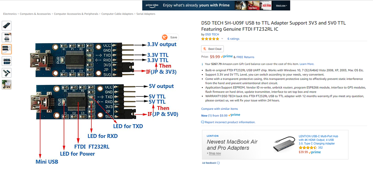
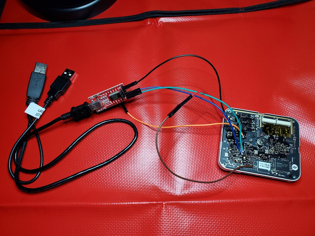
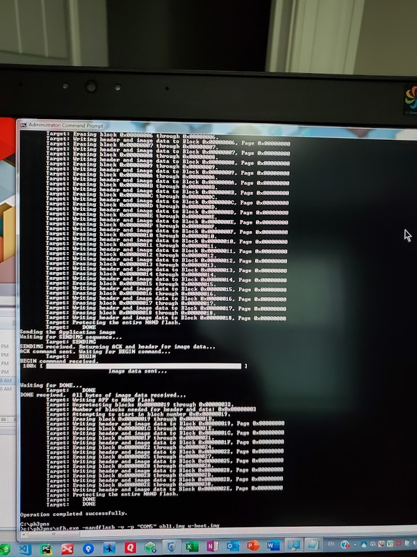
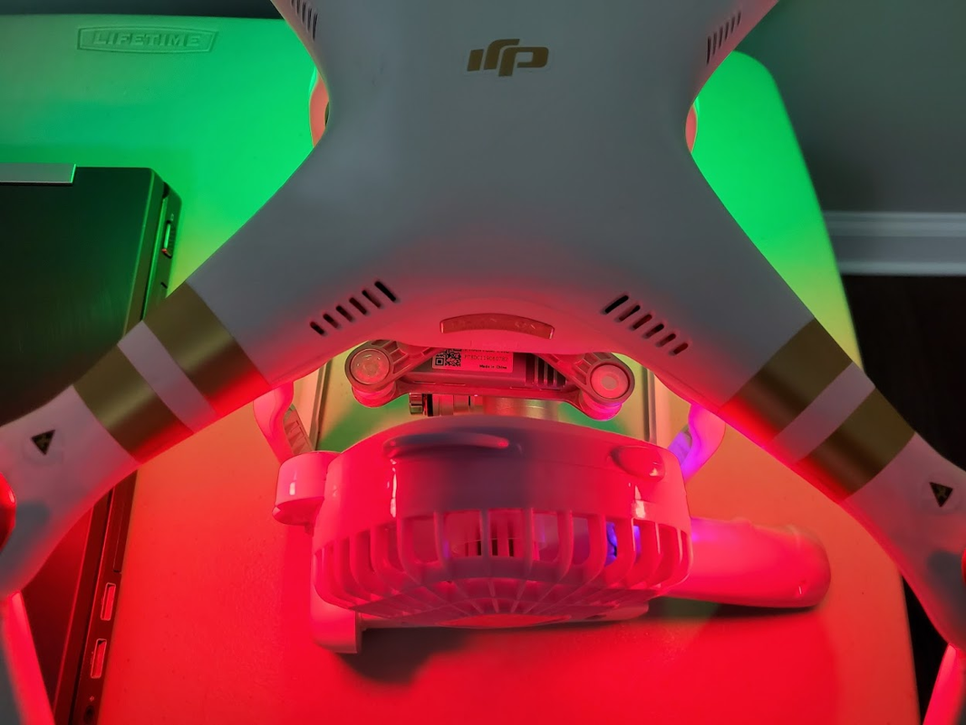
My P3Pro video feed is working after following your instructions to Flash the gimbal board. The only issue I had with it was not putting your files in C: (not in folders) and not turning on 'administrator privileges' in CMD on Win 10 pro

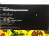
[00028872]Firmware upgrading[1]...
[00029739][08 00] Firmware upgrade start...
[00605000][08 00] Firmware upgrade finished successfully.
[00605092]Done.

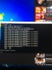
[00605180]Version checking[2]...
[00605310][03 05][00] v34.2.0.9 -> v34.2.0.9
[00605572][03 06][00] v2.4.20.50 -> v2.4.13.0
[00605677][04 00][00] v1.48.0.0 -> v1.41.0.0
[00605852][11 00][00] v1.8.0.0 -> v1.7.15.1
[00606004][12 00][00] v1.13.0.0 -> v1.10.0.0
[00606166][12 01][00] v1.13.0.0 -> v1.10.0.0
[00606324][12 02][00] v1.13.0.0 -> v1.10.0.0
[00606458][12 03][00] v1.13.0.0 -> v1.10.0.0
[00606616][15 00][00] v1.1.2.0 -> v1.1.2.0
[00606779][17 00][00] v1.1.1.7 -> v1.1.1.7
[00606955][17 01][00] v1.0.2.7 -> v1.0.2.7
[00607065][19 00][00] v1.0.8.96 -> v1.0.8.96
[00607164][01 00][00] v1.32.5432 -> v1.29.4920
[00607255][01 01][00] v1.32.5432 -> v1.29.4920
[00607361][08 00][05] v0.13.0.7 -> v0.13.0.7
[00607487][09 00][00] v4.1.0.0 -> v2.13.0.0
[00607579]Packet upgrade finish successfully.


PLEASE can anyone tell me which Firmware is the best to up-grade to as I've put: P3X_FW_V01.07.0060.bin as a starting point?
I've read that latter updates were becoming a little restrictive in terms of reception and flight distance?

THANK YOU (-:
 
I had to do this again (for the second time) two days ago. It is still a **** ton of work, but it is a magical fix and I am always amazed to see my video stream working again. Again, I did not use my drone in about four months, so I lost the firmware. Anyone know if there is a better fix, like soldering a cap or a battery onto the board to buy more time?
 
I had to do this again (for the second time) two days ago. It is still a **** ton of work, but it is a magical fix and I am always amazed to see my video stream working again. Again, I did not use my drone in about four months, so I lost the firmware. Anyone know if there is a better fix, like soldering a cap or a battery onto the board to buy more time?

No , just power it on every month.
 
No , just power it on every month.

Right, that is what I am trying to avoid. I do not use this drone much and I travel a lot (or used to before Covid), so I forget to power it on. I get that some NAND chips degrade with bad blocks over time, but why does powering it on manage the bad blocks better? Is it just the act of getting Vcc in the chip that keeps the blocks good or does it do a scan for bad blocks and reallocation when booting up? I thought about running a seven wire connector off the board to make flashing easier, but that seemed too messy and the solder points too fragile. I thought about just running the 5v and Ground and putting it on a trickle charger. Would that work?
 
I get that some NAND chips degrade with bad blocks over time, but why does powering it on manage the bad blocks better? Is it just the act of getting Vcc in the chip that keeps the blocks good or does it do a scan for bad blocks and reallocation when booting up?

It doesn't exactly do a 'scan'. If during read, a block takes longer than expected, it is marked as 'weak' and either refreshed or replaced by a different block. Even if it doesn't, it may get replaced/refershed based on i/o count - there's special hardware which checks how many times that happened. The blocks also have EC (error correction) data, and if this data is used to fix the values, that's also call for action.

Personally, I'm not booting my drone too often. I only test it before expected use, leaving myself a day in case it does turn out to need service. Ie. before this spring, I didn't booted it for over 6 months. Turning it on decreases the chance of an issue, but still doesn't eliminate it. I sometimes do turn it on when I'm making sure batteries won't get completely depleted, but that's all.
 
  • Like
Reactions: Mark The Droner
Ok ???. Got it figured out! Good thing I’m not in the computer business! I’d starve to death! But now I can flash a P3P gimbal board to fix the no image transmission issue ?
 
This forum amazes me all the time, last time I logged on was back in 2015/16 and my P3P is still practically brand new but was collecting dust underneath my bed due to family and work commitments. My mates was gassed about his small little DJi and I remembered I had a near new P3P under my bed amd decided to get it out and behold I had no image transmission, tried updating and stil nada, found this thread, done what I had to amd got into the trouble of a bad chip as per the pdf BUT guess what, I went to disconnect the serial USB and touched the cable that was soldered to Boot0 amd Boot1 and the CMD screen changed and next it started updating tge UBL1.IMG file and voila my P3P is back alive ?
 
hello guys, i have exactly the same trouble like charbel20 , i will answer him it is fixable but youneed some help from expertise on this thread cause i fixed my gl300A transmitter by a similar way i referred to a similar method on YouTube done by a very nice guy Terry
To view this content we will need your consent to set third party cookies.
For more detailed information, see our cookies page.
but that fix is for the transmitter now on the p3pro gimbal it seems that the flashing is much more tricky and needs some assistance to people like me and charbel... now what i did so far i started the same method outline in this thread i used a usb to ttl module( the same that i used to flash gl300A) imade the connection just like described here
To view this content we will need your consent to set third party cookies.
For more detailed information, see our cookies page.
but i faced a problem in the method of flashing the gimbal , the putty is not reading it on the same ttlusb i used to flash the gl300A, i powered the gimbal board from the ftdi(ttl usb in my case) it self, when i use the 3.3v the ttl will not be defined as a com port( unknown device) and will not launch the putty on that port, when i use the 5v option i t opens the comport in putty and the board status led blinks green for some time then red but no serial data received on putty?! i tried the ftdi32 same result so kindly i will proceed by posting every step i proceed to asking for help in case i got stuck ... as i said this fix is tricky and may need some times the hardware like dm365 chip replacement..
 
If you follow @SunsetCatcher instructions exactly, you will get the process completed.
You don’t use pUTTY to do this. And yes, the 08 15 modules not detected issue isn’t always fixed by just doing this flashing process.
 
hello guys after rereading this whole thread , i attempted our friend sunset catcher method, but i reached the point i will attach a screen shot of
Untitled1.jpg
 

Members online

No members online now.

Forum statistics

Threads
143,066
Messages
1,467,358
Members
104,935
Latest member
Pauos31