That looks like the firmware on the r/c needs to be updated by looking at the picture. That would also explain why the led’s are like that. If the a/c would link together before, but shows an ESC error now then there may be a chance that the 1.11.0020 firmware may have caused it. There are some threads on this forum that talks about it and a possible fix. Maybe the update to the r/c will fix it all.i fixed this bricked craft according to sunset catcher method, and upgraded it to firmware 01.11.0020 and i have a good other working p3p with its transmitter gl300B on firmware 1.8, before the fix i binded the bad p3p to this working transmitter , i was able to arm in atti mode and motors spin but got nothing on goapp, now after the fix this is the image am getting but the fixed p3p cannot arm it states escerror restart plane and if doesnot work contact dji. the image some times get dim(like in case of low rssi). some thing to note when i bound the ac to this transmitter the transmitter led status is not solid green, but blinking green red, while the aircraft connection led status next to bind button is solid green. what to do


You are using an out of date browser. It may not display this or other websites correctly.
You should upgrade or use an alternative browser.
You should upgrade or use an alternative browser.
No image transmission signal - P3P
- Thread starter AsiaFlyer
- Start date

just to make sure i got you correctly! can ifrom the firmware 1.2.6 on transmitter run update to 1.11.20 using usbsd card adapter directly???I updated my remote using a thumb drive. A sd card usb adapter works too. With the 1.11.20 firmware you have to use the usb port.
or i should do as some one mentioned go to 1.3.4 then update via app to 1.11.20????
Follow what @Oso posted in post # 237 and it should all work for you.just to make sure i got you correctly! can ifrom the firmware 1.2.6 on transmitter run update to 1.11.20 using usbsd card adapter directly???
or i should do as some one mentioned go to 1.3.4 then update via app to 1.11.20????
well after some 7 nights of reading on the firmware things upgrades and down grades and after reading a ton on fw 1.11.20 for p3p ,, i am considering (not have taken the decision yet) to try a downgrade from 1.11.20 to 1.10.90 this will make me get rid of flight distance restriction and esc error msg and 1.11.20 its self; and prior to that i want to ask oso and all others who have a deep look into fw versions my transmitter fw is gl300A not GL300B or C it is currently on firmware 1.2.6 or the one that comes after it , why?? cause i i once connected it to a go app of a friend and he long pressed upper right box on screen in first page of goapp and he yelled 1.2.6 ,but i think what pops up in that method is previous not current fw... now what firmware i should go to from 1.2.6 or its successor on gl300A to start updating by app( i have read that on gl300B i should go to 1.3.2 to start using app transmitter update and on GL300A i should go to 1.4 to start using the app) but
first i didnt find ana link to gl 300A firmwares hopefully some one provides links .
second after i finish the update by usb when i use update via app does all later to my transmitter firmware show up or the app forces me only to the latest firmware(i think 1.9.2)????? and third is it easy to roll back from latest transmitter firmware 1.9.2or it may brick the transmitter???
Last edited:
i edited the post hopefully its readable nowTrying to read that makes me appreciate punctuation.
ok so i was already trying firmware update to 1.11.30 to solve esc error status... what do you say could i roll back to 1.11.20 by debug or try forced update to 1.11.30(i ment by forced update to put the firmware on sd to ac and turn it on while pressing link button)
maybe.what do you say could i roll back to 1.11.20 by debug
If ESC will respond, there is no need to force. It should update normally.or try forced update to 1.11.30
If ESC won't respond, you can't convince it otherwise by talking to Ambarella. No matter what you do to Ambarella, it can't fix a chip which is not responding.
i have no choice at this point but to try to roll back to 1.10.90 ...before flashing the gimbal board i connected this AC to a gl300b and i was able to arm in atti mode since i was indoors.. but after the flashing since i knew that what happened to this p3p happened with prevous owner trying to update to 1.11.20 so i had no chance but to continue the update , now a failing update to 1.11.30 that showed in 3min only the long sound with red gimbal led on ... how do i proceed ? should i put 1.11.20 on sd card with debug? or what
This is not a correct thread to discuss ESC issues.
You can try downgrading. But I suspect you have physical damage on ESC Center board.
You can try downgrading. But I suspect you have physical damage on ESC Center board.
am too sorry i deviated from topic but since i felt confident with the experience of guys here and felt am too close to finish the fix... i will start a thread hopefully to get to an end on this hopefully guys here will help me there and others facing same problem may find it helpfull heres thread link phantom 3 pro open heart--- gimbal flashing , fw 1.11.20, esc status error
hello guys, I started an attempt to fix a no vid gimbal i bought following the same procedure i used before provided by our freind sunset catcher
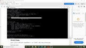
, similarly the guy in vid provide a link to dji repair tool to down load comparing to sunset catch tools( it worked for me earlier), it seems the exe file and images are same for both ways but the video link tools seem to have additional files?? , i followed the pdf steps connections and i reached the point in image attached below below , it mentions that the chip is write protected! i didnt run putty i just used the ftr ftdi adapter ! what made things worse i felt one wire on the bt0 pin on gimbal poped and to my fear both bt0 and bt1 points poped with there solder joint point and ripped off the board (those are the two points that are jumped to the 3.3v)"though i didnt apply any force to them now am in a double trouble!! where can i solder ulternitavly to bt0 and bt1 to get board to boot mode ?? and what is the trouble that prevented a full successful flash??? thanks in advance
Attachments
Last edited:
I also had a couple gimbal boards that had the ‘nand write protected’ problem also. On the nand chip one of the solder balls is responsible for the write protection, and it is not making contact with the gimbal board. You could try to reflow the chip, but I had no success doing that. Replacement of the nand chip was necessary.hello guys, I started an attempt to fix a no vid gimbal i bought following the same procedure i used before provided by our freind sunset catcher , similarly the guy in vid provide a link to dji repair tool to down load comparing to sunset catch tools( it worked for me earlier), it seems the exe file and images are same for both ways but the video link tools seem to have additional files?? , i followed the pdf steps connections and i reached the point in image attached below below , it mentions that the chip is write protected! i didnt run putty i just used the ftr ftdi adapter ! what made things worse i felt one wire on the bt0 pin on gimbal poped and to my fear both bt0 and bt1 points poped with there solder joint point and ripped off the board (those are the two points that are jumped to the 3.3v)"though i didnt apply any force to them now am in a double trouble!! where can i solder ulternitavly to bt0 and bt1 to get board to boot mode ?? and what is the trouble that prevented a full successful flash??? thanks in advance
As far as the two boot pads, there is an alternative location to solder to, but, it is quite difficult to achieve.
hi Diver hopefully you and all guys here are good , where is that other location for bt0 bt1 soldering? second i noticed that the files the german video of flashing provides have other than the images and the texas instruments provide ,could those tools over come that write protection issue?I also had a couple gimbal boards that had the ‘nand write protected’ problem also. On the nand chip one of the solder balls is responsible for the write protection, and it is not making contact with the gimbal board. You could try to reflow the chip, but I had no success doing that. Replacement of the nand chip was necessary.
As far as the two boot pads, there is an alternative location to solder to, but, it is quite difficult to achieve.
i bought earlier another broken gimbal i was buying batteries and the seller offered it for free it has the flat cable cut, now i took ir apart to take out the flat cable from the gimbal that ripped off that i will put aside , this gimbal has two leds one in front as usual and one in the back next to the dm365 is this normal, am used only to see one led in front the one we look at during update or sd card
Last edited:
I’ve had a few boards that had the extra LED on it, it’s just another variation of this model of gimbal board.hi Diver hopefully you and all guys here are good , where is that other location? second i noticed that the files the german video of flashing provides have other than the images and the texas instruments provide ,could those tools over come that write protection issue?
i bought earlier another broken gimbal i was buying batteries and the seller offered it for free it has the flat cable cut, now i took ir apart to take out the flat cable from the gimbal that ripped off that i will put aside , this gimbal has two leds one in front as usual and one in the back next to the dm365 is this normal, am used only to see one led in front the one we look at during update or sd card View attachment 121209check..
I’ll get the board that I traced out the alternative boot pads and take a couple photos of it for you. It’ll be later in the day before I can get to it.
take your time and thanksI’ve had a few boards that had the extra LED on it, it’s just another variation of this model of gimbal board.
I’ll get the board that I traced out the alternative boot pads and take a couple photos of it for you. It’ll be later in the day before I can get to it.
Similar threads
- Replies
- 5
- Views
- 955
- Replies
- 8
- Views
- 2K
- Replies
- 3
- Views
- 10K
- Replies
- 10
- Views
- 5K


Recent Posts
-

-
 North Jersey, Very new old guy trying to get off the ground with a P330Z Phantom 2
- Latest: captainmilehigh
-

-

-
