- Joined
- Jul 28, 2019
- Messages
- 313
- Reaction score
- 266
- Age
- 40


well at least if you do with new shell you can reinforce arm from inside the shellAnd in the pictures it only shows one scratch but the are at least on two holes or all 4 on each arm. Thats why I think its like from it dragging across the mold or something . And they are all going in the same direction for the most part.. weird
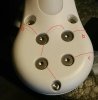
You aint kiddin stress'd thought I'd destroyed my best flierMan thats crazy! Thats no good! We definitely need to figure out a different solution. My new shell came today and I have some interesting news it seems to have the lines right were the cracks would form. Like light scratches it looks like from the molding process or something. Almost like predetermined cracks like im scared to put this thing on and now im scared to order the motor mount plates... what to do. They might be nothing . Sorry they messed your motor up even for a second. I know that is stressful. Which brings me to this question if your flying part 107. And you know your craft has stress cracks and do a preflight check are you in the wrong if you let it fly with stress cracks? Or only wrong if something unfortunate happens? Or are you guilty just putting it in the air? Heres the pics btw
With the FAA you the PIC are responsible for everything if your firmware is not up to date & that's the cause of an accident or the cracks are whatever caused it and you flew it knowing that you're in deep doo dooWhich brings me to this question if your flying part 107. And you know your craft has stress cracks and do a preflight check are you in the wrong if you let it fly with stress cracks? Or only wrong if something unfortunate happens? Or are you guilty just putting it in the air?
Looking at the pictures those seem to be some sort of casting marks? Is there any evidence of the on the other side, do they seem to go right through?Man thats crazy! Thats no good! We definitely need to figure out a different solution. My new shell came today and I have some interesting news it seems to have the lines right were the cracks would form. Like light scratches it looks like from the molding process or something. Almost like predetermined cracks like im scared to put this thing on and now im scared to order the motor mount plates... what to do. They might be nothing . Sorry they messed your motor up even for a second. I know that is stressful. Which brings me to this question if your flying part 107. And you know your craft has stress cracks and do a preflight check are you in the wrong if you let it fly with stress cracks? Or only wrong if something unfortunate happens? Or are you guilty just putting it in the air? Heres the pics btw
Whew those are bad mine not near that bad thats a new shell for sure"it's an old one I am disassembling to make a balance adapter with!! " Crafty beep beep. Can you photograph your progress with a view to making a thread about a DIY balancer.
I was looking to buy a "mint" P3adv .......until I saw those cracks shown in the attached, a couple of the other mounts had lesser cracks. a & b went right to the edge of the shell and could be seen flexing, I can't remember about c.
Thanks for sharing I like itMy balance adapter using two "no longer working": 2312A - one CW, one CCW
Disassemble motors - can be challenging but a bit of brute force here and there works and you'll be left with the two rotors comprising the ends, where the threads are, and the rotor housing where the magnets are. Remove the magnets (hard!) and cut off the housing tube from the ends. You now have the threaded ends with a 2cxm long nearly 4mm diameter shaft (where the bearings were).
I used a 15cm length of 4mm ID good quality brass tube, polished and checked for true.
thoroughly clean the tubeID and motor shaft, apply a tad of glue and push the shafts into each end of the tube.
Should be job done.
View attachment 114134View attachment 114135View attachment 114136View attachment 114137
The casing where the magnets sit is magnetic, possibly iron, and the end bit where the threaded spindles are is aluminium. Yes I cat them off by spinning them in my small lathe and using a hacksaw!Neat, as I said, crafty beep beep ???
I am wondering if heat or a solvent might soften the glue that presumably holds the magnets in place, is the magnet holding 'sleeve' part of the spoked bit? It looks as if there might be saw marks on the face of the spoke 'rim'
Be careful what paint/primer you put on. These are some sort of moulded plastic and some paints will have a solvent in them that could cause deterioration of the plastic!!!Is this the newer design?? Dont know much about them. I dread puttng it on. Gotta paint it first. Should i primer the shell? Or is that extra weight? The paint i use covers good. Never used primer before and never had a problem. Also that balancer is super sweet. But if you already have the base.. why not order or make another rod. Unless those motors were burnt up. And wouldn't putting even the slightest drop of glue in the wrong spot on the rod mess up the balance? I need a balancer bad though
Heard that! Thanks cheddarman! Your a wealth of knowledge! I thought i heard that somewhere before. Do you happen to know what the solvent is?? I will test the old shell before hand. I didnt want to tell my secret.. but heres what i use. Ive used it on plastic bumpers and car parts so safe on that at least. Awesone stuff. Lays down super smooth and dries fast as all get out. Ill probably pass on the primerBe careful what paint/primer you put on. These are some sort of moulded plastic and some paints will have a solvent in them that could cause deterioration of the plastic!!!
It gets a terrible write-up on Amazon, especially if used in tight spaces - the UV light cannot get in to cure it!Speaking of glue, has anyone tried "Bondic" or any UV light curing glue? I heard it's so easy to apply and welds broken/cracked plastic really well. You can manipulate it however you like while in liquid form and once you put it under UV light, it hardens.
I agree 100 %Hi all,
I have been using the cnc aluminum mount plates on every Phantom 3 I own for quite some time now. I put them on whether there are stress cracks or not. The ones that have cracks are not getting any worse. The ones that are crack free, are still crack free. I have flown them with and without the plates attached. In my humble opinion, there is no affect in performance by having them on. I personally like the look of them,, and they are a lot easier to install than replacing a new shell, and less money also. And, after you have replaced the shell, you eventually have another phantom with stress cracks! My opinion.


We use essential cookies to make this site work, and optional cookies to enhance your experience.