- Joined
- Jan 25, 2015
- Messages
- 7
- Reaction score
- 0


Hi,Got P3S yesterday. Not happy with range. Considering I also live in dense residential area with hundreds of wifi networks around.
So I tried to hack(?) in to it to see what can be done.
I was so far successful getting inside via FTP :
...
ok, I will do so and post everything that I find out.Rhino.de - please let me know if you find out how to check the switch state from a script, as I'm trying to do something similar. I have a set of amplifiers that I sometimes connect, and sometimes don't, depending on the flight. Without the amplifiers FCC mode (I am in the US) at 27 dBm is fine, but the amplifier input is max 23 dBm and so when using them I need to reduce the TX power of the remote. Right now I have to do this manually via telnet each time, so it would be very nice if I could hold down a button while powering up the RC to select between the two modes.
I have explored /sys/devices a little and wasn't able to find any obvious way to get the button state, but I am sure there is a way - after all apsrv does it!
-Adrian
")
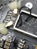
So the wire attaches to the centre point just left of that chip and then to either one of those points at the top or bottom right of the board?Confirmed to work properly
But to make the mod easier as this is very small, then I made it a bit easier.
Rather than soldering the very short wire on the very very tiny dots for the chip
I soldered the wire on the end of the SMD capacitor close to the chip and then to only one of the antenna capacitors.
The soldering area is larger and easier to solder to than the tiny dot.
Also the wire is longer, so it does stick on one end even the other is being soldered.
That is not the case if you have 2mm wire as the original mod.
Just solder small/wire-wrap-wire on the points shown as #1 in red or as #2 in blue.
I know it might affect the RF part, but it for sure did improve the range dramatically.
View attachment 97369
Excellent, thank youYes exactly
Bigger soldering points so it is workable for humans.
I dont know, but would guess the antennas are for 2 and 5 Ghz meaning the switching in the chip is to select the proper antenna for the frequency in use.
But the antennas are good (enough) for either frequency.
did u get the part ???Is there a part number for this chip????
I think I got herYes exactly
Bigger soldering points so it is workable for humans.
I dont know, but would guess the antennas are for 2 and 5 Ghz meaning the switching in the chip is to select the proper antenna for the frequency in use.
But the antennas are good (enough) for either frequency.
IT WORKED, IT FRIGEN WORKED!!Yes exactly
Bigger soldering points so it is workable for humans.
I dont know, but would guess the antennas are for 2 and 5 Ghz meaning the switching in the chip is to select the proper antenna for the frequency in use.
But the antennas are good (enough) for either frequency.


We use essential cookies to make this site work, and optional cookies to enhance your experience.