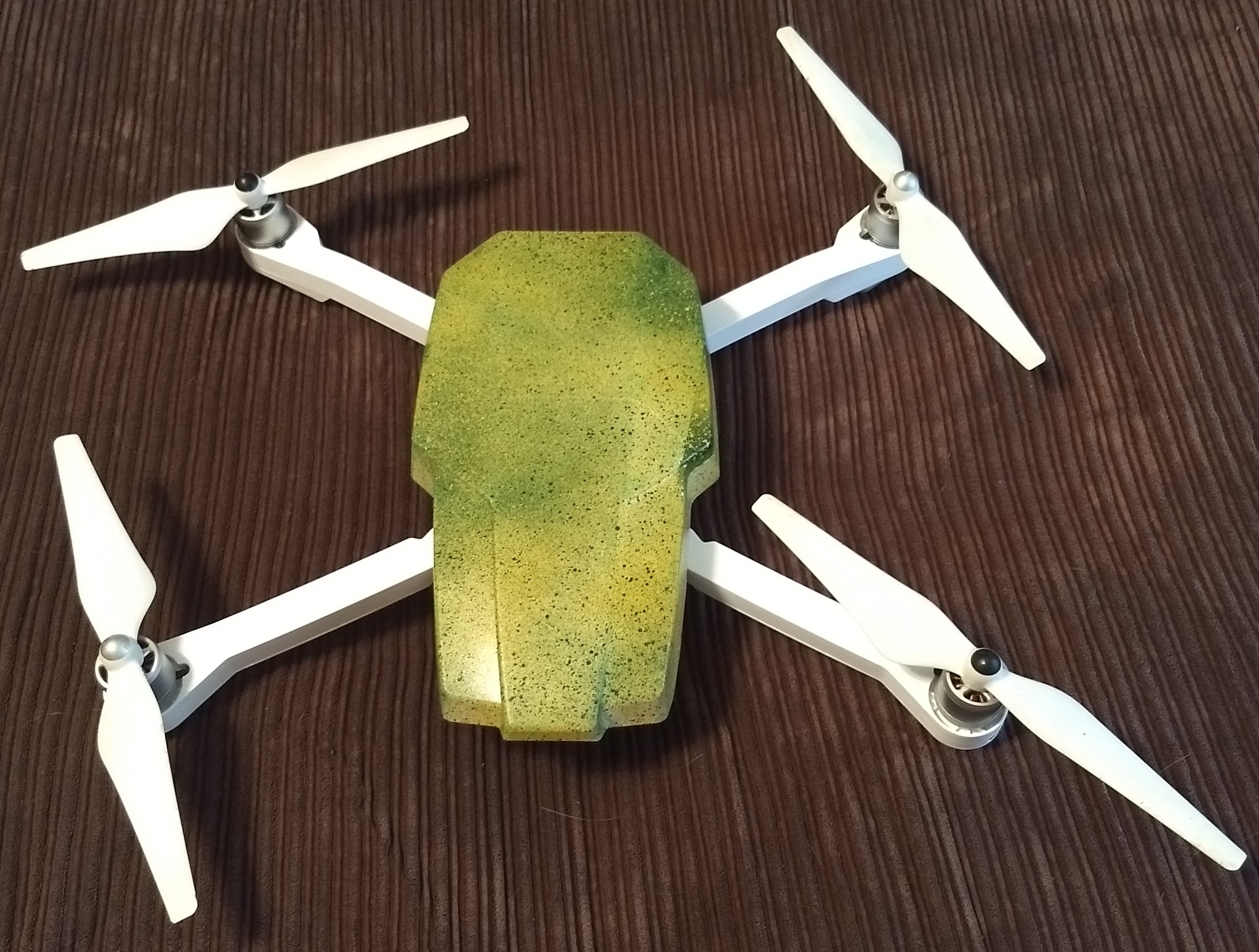
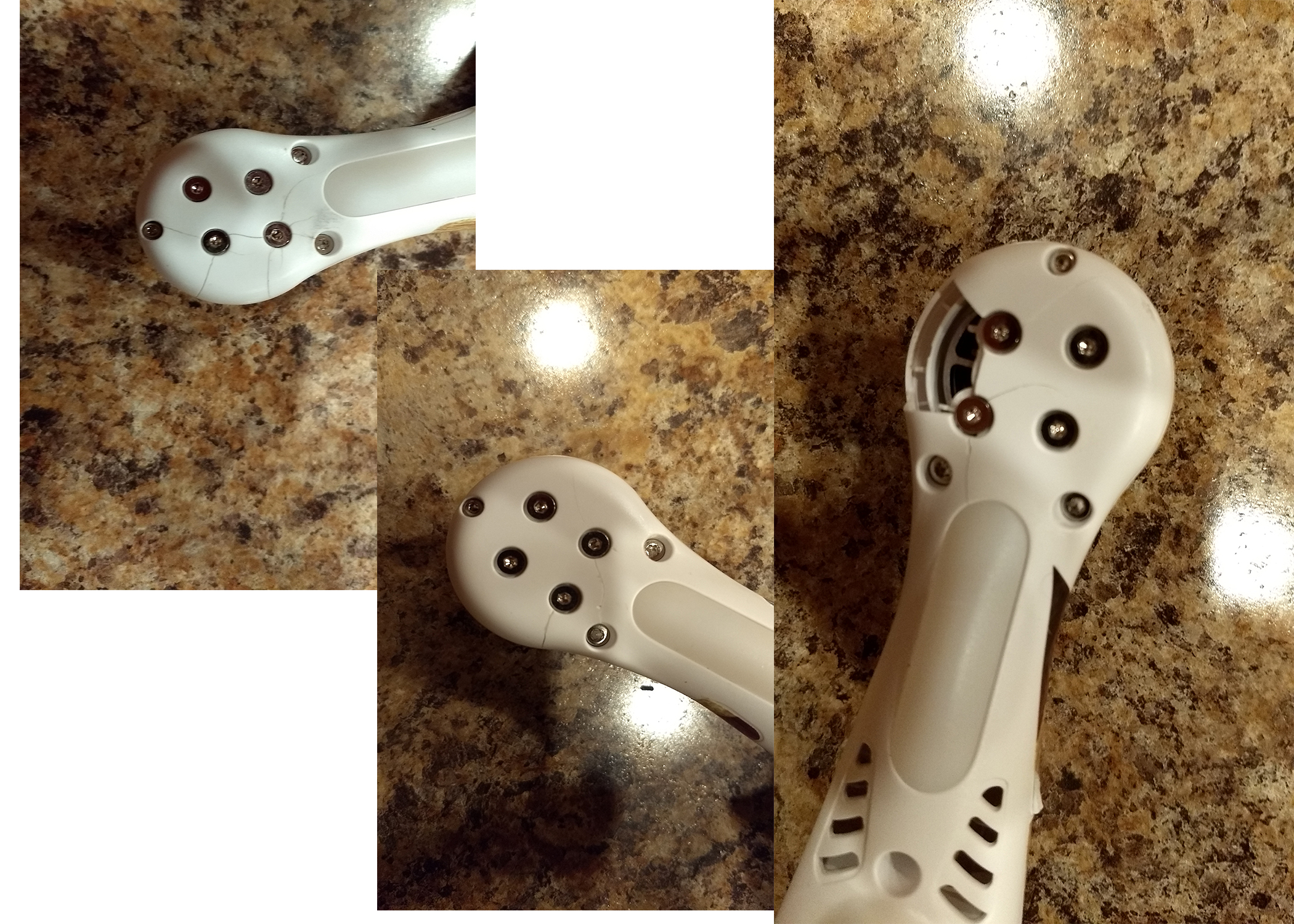
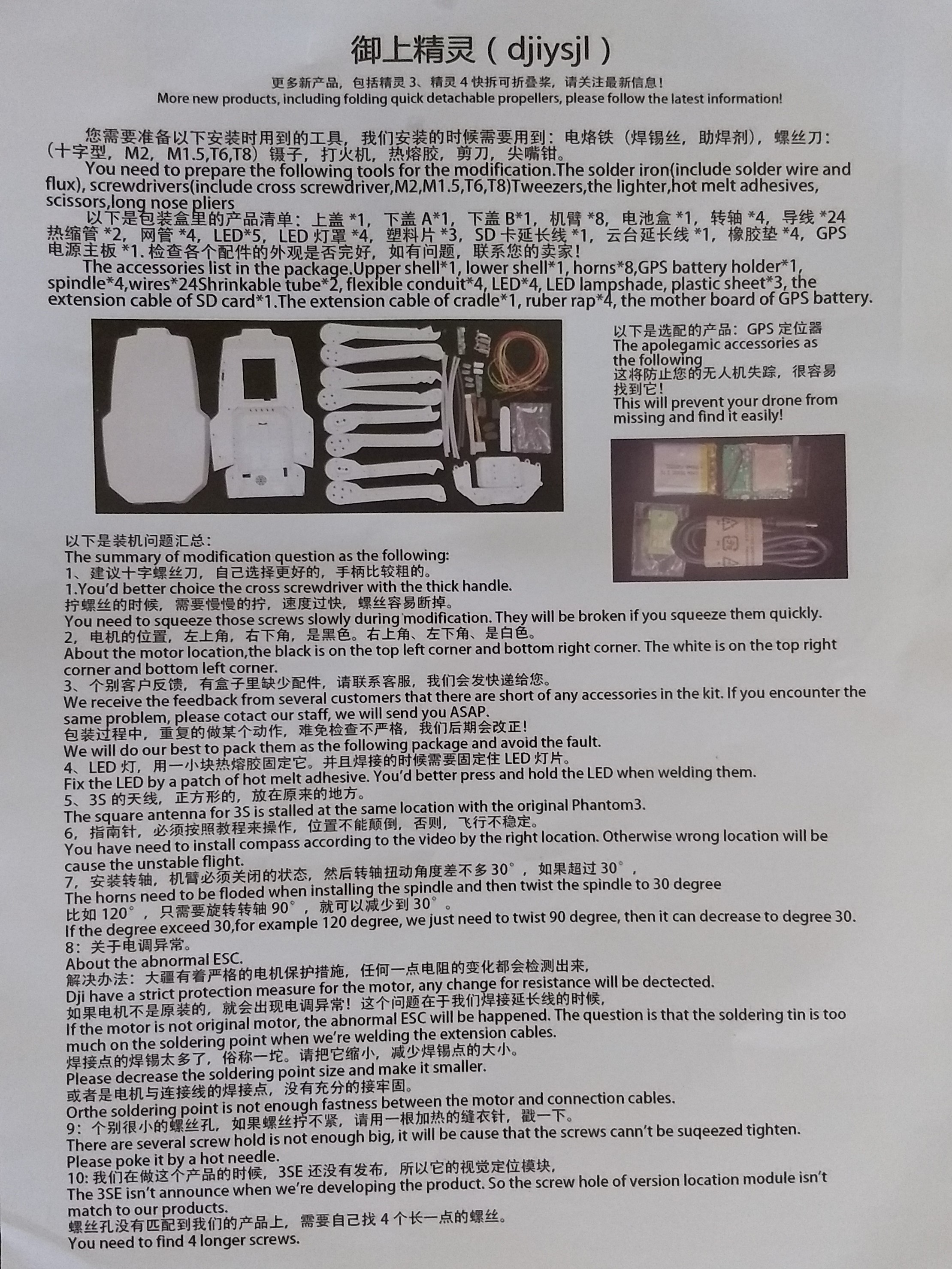
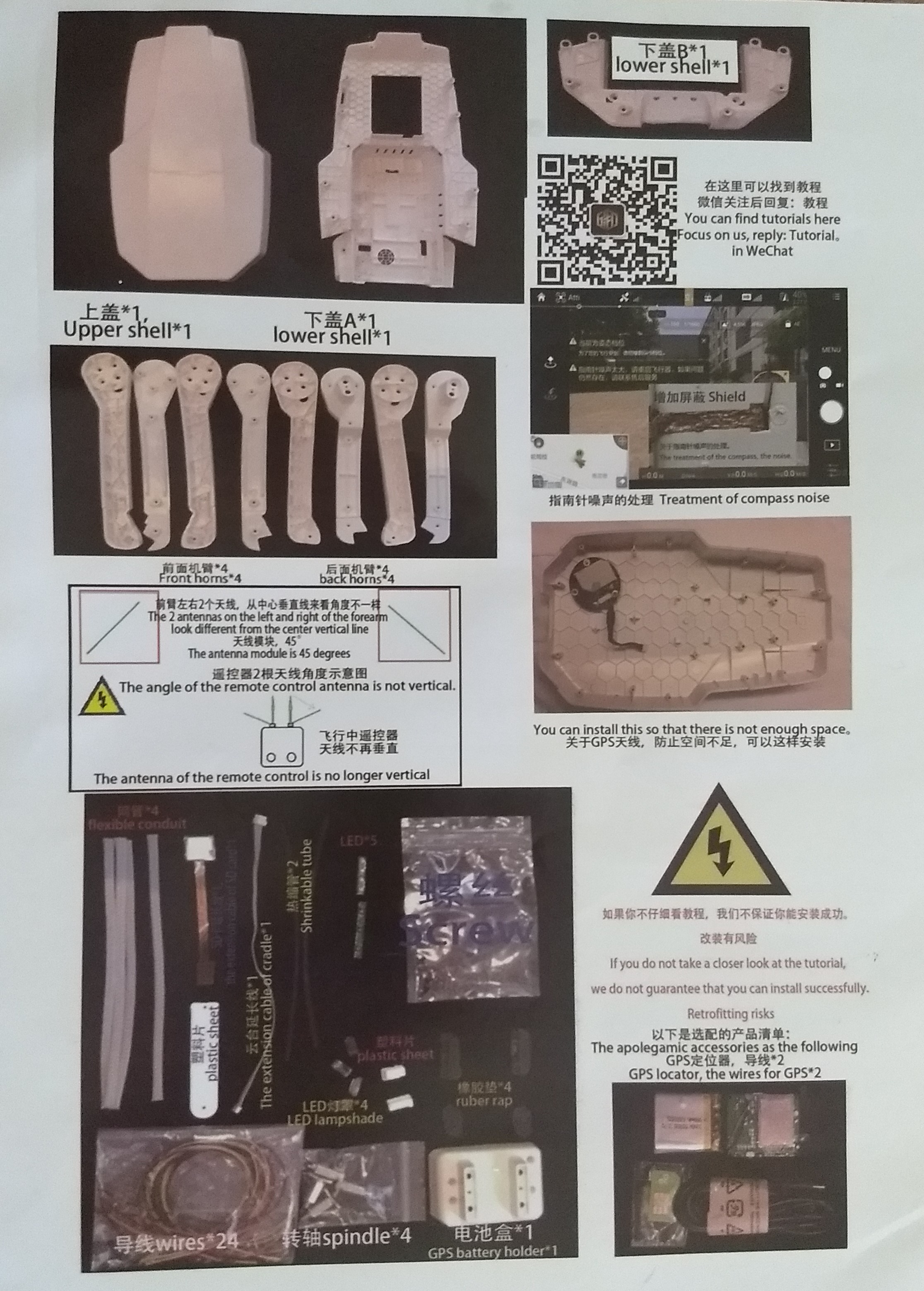
I ran into motor mount issues and decided to go with the conversion kit instead of a new shell. I'm very happy with the results! Thanks so much for the people in this forum that shared their helpful tips and tricks for the conversion. I really don't have any others to add - it appears that the manufacturer is paying attention and improving their product/instructions though as some of the tips shared here now appeared on an information sheet shipped with the conversion. My only complaint with the kit is that the soldering iron didn't work but I had one anyways. On my maiden flight I actually got better distance than I did before the conversion! I loaded a Litchi mission to send it out and see how far I could get signal and it got choppy at about 3,100' flying 125' off the ground in an area with lots of wifi in the area. Video cut out at about 2,900' away, I was not flying line of site.
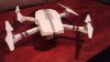
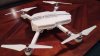
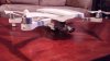
IMG_20170720_185832273
- dapack
- 3
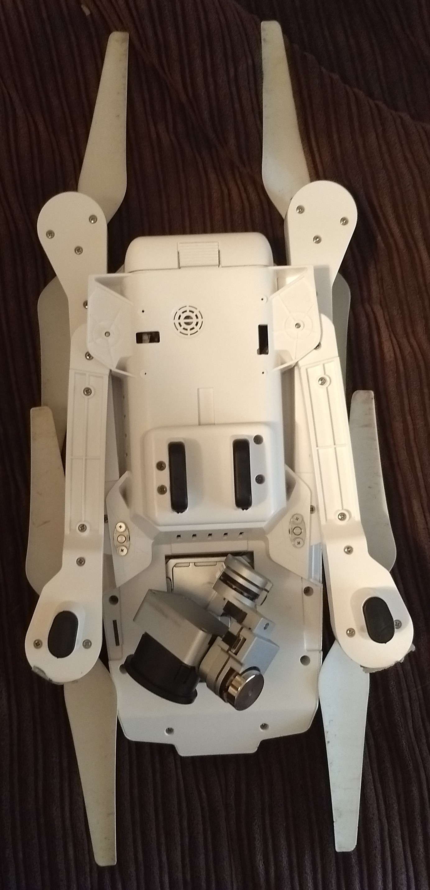
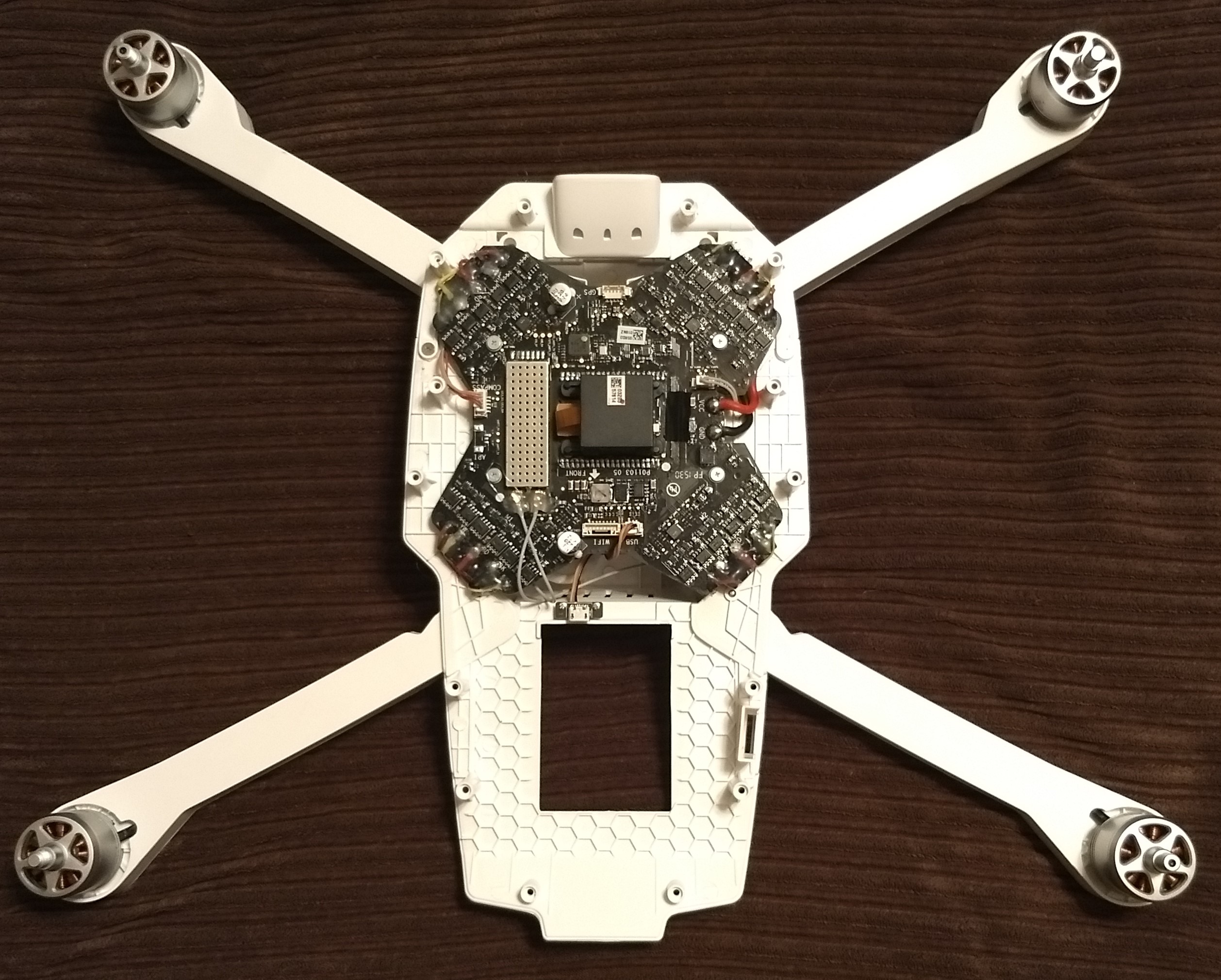
Inside bottom of Phavic. Sorry no upper shell pics - I did mount GPS off center and the camera...
Last edited: