Phantom 3 Professional , Need high dev. picture of mainboard a broken mainboard ( Identify SMT ) .. :)

Joined
Apr 11, 2020
Messages
13
Reaction score
5
Age
43
Hello there :blush:

I have a Phantom 3 Professional. She currently does not start because I had a nice landing in the water :)
I do forensic data recovery for water damaged devices and was able to replace every defective part except one.
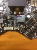
Would you please help me with a high definition picture of your main board to identify this part ?
The only way you could read the number on this part with a USB microscope would be to wet it a little with
a Qtip and shortly before it is dry again, you can ready the numbers and letters on it. I believe mine starts with a number 2 .... ( Marked in Yellow )
Looks like a DIP , maybe a voltage regulator..... ? Every other part is working well :)
If you could identify :)the part or maybe have a defective board that I can take this part from that would be awesome !!! :)

drone.png


If you could help me that would be awesome :)

Thank you much !
Kind regards
Frank
 
"200"?

In v7 board it had 3 legs, and there was no coil nearby.
So I think it was a linear regulator in v7, and was switched to buck converter in v9.

1586658252807.png
 
  • Like
Reactions: gianasisters-c-64
Hello Team :) I received the Board from KachemakDiver ? ❤❤❤

Many many many thanks !!!!


I used a Hotair station to remove the failed component marked "200" from the defective Board that he send me. I noticed that he solder they use is quiet stronger than "normal" solder. What I mean is that it does not flow using the normal temperatures for SMT rework on similar electronics.

A temperature of 423 Degrees for about 10 seconds with an Airflow of 1 out of 8 on a pre heated board finally released the component. The reason for the low airflow was the other close contact SMT Parts and me being out of Kapton Tape ;) .

Do yourself a favor and mark one leg of the component being removed. It turns out they don`t like heat very much and any markings on the chip like the number"200" on my part was totally gone... ?. Believe me , no microscope is going to help you.. lol
Anyways. The removal process form the Board that KachemakDiver has send me is now done.
I am going to get some Kapton Tape and some alcohol to clean my own board and then I am going to place the chip from KachemakDivers Board on to my Board. It`s been an easy journey so far ...
FORUMPICS.png

As you can see there happened to be a nice explosion , and yes that is the remainder of the Qtip and solvent that I used. LOL ( I am in my improvised Lab at the moment )

If GOD let me live another day then I will update tomorrow :mask:
 
  • Wow
Reactions: brigerdrones
Hello Team :) I received the Board from KachemakDiver ? ❤❤❤

Many many many thanks !!!!


I used a Hotair station to remove the failed component marked "200" from the defective Board that he send me. I noticed that he solder they use is quiet stronger than "normal" solder. What I mean is that it does not flow using the normal temperatures for SMT rework on similar electronics.

A temperature of 423 Degrees for about 10 seconds with an Airflow of 1 out of 8 on a pre heated board finally released the component. The reason for the low airflow was the other close contact SMT Parts and me being out of Kapton Tape ;) .

Do yourself a favor and mark one leg of the component being removed. It turns out they don`t like heat very much and any markings on the chip like the number"200" on my part was totally gone... ?. Believe me , no microscope is going to help you.. lol
Anyways. The removal process form the Board that KachemakDiver has send me is now done.
I am going to get some Kapton Tape and some alcohol to clean my own board and then I am going to place the chip from KachemakDivers Board on to my Board. It`s been an easy journey so far ...
View attachment 118202
As you can see there happened to be a nice explosion , and yes that is the remainder of the Qtip and solvent that I used. LOL ( I am in my improvised Lab at the moment )

If GOD let me live another day then I will update tomorrow :mask:
WOW, that chip was messed up. Hope the board cleans up so as to be successful with installing the replacement chip?
 
That`s going to be fun :) lol about 1 am here.... :) I will update tomorrow.I am reading myself into the problem with your board right now... :) :D :D :D Have a good night (morning ) lol
 
:D :D
Gooood Morning !

The Soldering Job went well and the GPS started working.
Now whenever I try to take off it gives me the dreaded ESC Error.
I will investigate tonight ! (pictures will be posted ! )
If we can find out the reason for that we could make a lot of people happy :)
I am assuming a Mosfet or the IC that controls the voltage going to the mosfet.....
Since it took a quick dive in the water I am wondering if a shorted Motor ( or wrong resistance in the motor could cause the ESC Error ) ... I am going component level now and I will identify the logic behind the chipset to see if I can find a in that I have to put "high or low" to give the "OK" for takeoff.,,, lol I hope that made sense :D:D
( I did upgrade the firmware for the Remote control and Drone ;) no avail )

Kind regards
Frank
 
Good Morning Renevalencia :)
Thank you for your feedback :) ...
I tried both ways and no avail.
I will keep you all updated !

Kind regards
Frank
try the v01.11.0030 in the below link dude :)
 
  • Like
Reactions: gianasisters-c-64

Recent Posts

Members online

Forum statistics

Threads
143,090
Messages
1,467,569
Members
104,974
Latest member
shimuafeni fredrik