OKSTUV, GREAT tutorial on how to fix P2 Vision +. Mine sat for over a year and went to fly today but no camera visuals. I found out about the problem, and found your well-written tutorial. The instructions are long and daunting, but I am going to do it rather than replace the whole wifi module needlessly. I actually was reading through this thread trying to find the answer to a question I have on your instructions. It's not clear to me at step 2 which files I am supposed to be downloading when your instructions say "
Download the Flash utility and binaries for phantom 2 vision plus wifi module firmware" I clicked the link and see files but have no idea which ones I should use or what they are. As long as you are revising, this could use some clarification for those of us who aren't familiar. Can I also suggest if revising, to add pictures, or even better, video? I realize this may be more work than you originally planned and I don't know how donations are going, but it seems like the only real source in one clear place, so I have high hopes for you and your writing of the instructions that were figured out by Gaucho, andrew, and rmhome.
I am looking forward to this:
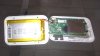
FT232RL FTDI USB 2.0 to TTL Serial Adapter Module for Arduino Mini Port 3.3V 5V | eBay
cheap alternative to the Tinksky FT232RL FTDI USB2.0 to TTL Serial Converter Adapter. I'm not in too much of a hurry. My batteries had swollen like crazy while stored too, so I can wait for the $3 tool to arrive from across the globe, lol.
Thank you for taking the time to write up the instructions and double thanks to gurus andrew, Gaucho, & rmhome. It's going to help a lot of people, more tha n already by far I think.