5v main esc board help..

hi,
problem, LEDs are not working. there is no 12v on the vcc line in the front left section. front right and back led vcc have 12v on the part. I wrote the voltages in the picture. front left vcc part and R right short-circuit in front right part.

P3X-ESC-top_VOLT_1.jpg
P3X-ESC-VOLT_2.jpg
 
Last edited:
Nice mapping!

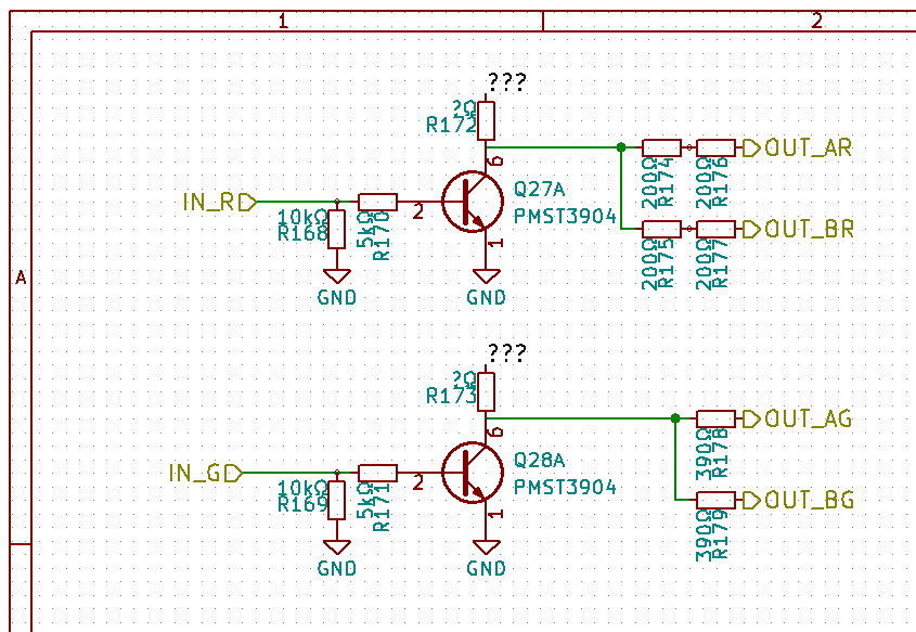
You found all four transistors - each of them switches one color of two LEDs. So we have 2 pairs of LEDS, and two colors - therefore 4 transistors.
So (as seen on rear LEDs) red goes (from transistor) through 400 Ohm resistance, and green through 370 Ohm? Looks like this is used to make same brightness of red and green LEDs.

I would assume the circuit for front LEDs should be identical to the one for back. So there should be one more 200 Ohm resistor before M1_R, and two more before M2_R.
Also, 370 Ohm resistors linking M1_G and M2_G to their transistor. When transistor is disabled, you should see VCC on output pin of the transistor. When transistor is enabled, that pin should be shorted to 0V (in theory it could also be shorted to VBATT, but I doubt Dji does such bad things).

To test whether a transistor is switching correctly, just short the M12_{RG} or M34_{RG} to 3.3V output or GND for a second, and check whether this causes the diode to light/disable. M12_* and M34_* are probably going through high resistance low power resistors before reaching the transistor base pin; so if you want to be safe, short the transistor base pin instead of M12/34 lines.

The +VBATT you have on the back does not sound correct. I would assume there should be only GND and 12V used around the transistor. But who knows.

EDIT: Wait, there is a schematic available on the project you inserted picture from:
full


So you have a schematic; then what are you missing?
 
Thank you for your interest. I will make checks and give information.
 
Last edited:
Thank you for your interest. I'm sorry for the loss of p3p. The p4 on the way to your table is gratifying. you use hope without any problems.

I do not know english. Google Translate. If there is a typing error, sorry.
I already have my P4P. I love the 30 minute flight time and collision avoidance.
 
Is there a friend who can measure voltages at vcc, r, g, tips at the esc terminal? Volts of m1, m2, m3 and m4 sections? m1 section (R), m2 section (VCC) tip, short circuit? I am having problems with this part. insoluble.
 
Is there a friend who can measure voltages at vcc, r, g, tips at the esc terminal? Volts of m1, m2, m3 and m4 sections? m1 section (R), m2 section (VCC) tip, short circuit? I am having problems with this part. insoluble.
As you can see on the schematic, R and G should be only connected to resistors. So definitely no short circuit between arms.
 
As you can see on the schematic, R and G should be only connected to resistors. So definitely no short circuit between arms.

only the m3 and m4 sections are linked in the schematic. The m1 and m2 sections have different connections. this can be seen in the picture I have shared before. It is very different from the schematic. my English is not good. I'm using google translate. I am sorry if wrong.
 
the device finally worked. As I wrote in my previous messages, m2 vcc part and m1 R part are connected. It was the right one. the front and back lights must be lit. My current problem was that the device could not detect the GPS. The EPROM on the GPS (25QDVSIG) is broken when the device is switched off. I put another one in place. but there is no software in it. Is there any software to share? Where can I find it?

IMG_20180803_203703.jpg
 
1,2,4,5,6,7 Does anyone know the connections of the feet? I tried to ignore my reports.

gps_forum.jpg
 
Last edited:

Recent Posts

Members online

Forum statistics

Threads
143,086
Messages
1,467,525
Members
104,964
Latest member
cokersean20