I am going to try to add 5 volts of power with the camera disconnected since I don't want to put it at risk.


You are using an out of date browser. It may not display this or other websites correctly.
You should upgrade or use an alternative browser.
You should upgrade or use an alternative browser.
5v main esc board help..
- Thread starter brhodz
- Start date
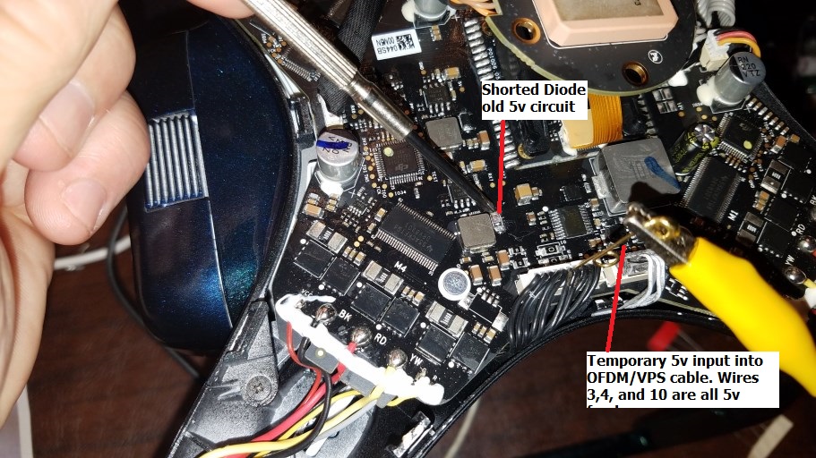
I FIXED IT!!!! I am so happy to have my bird flying again. I was right about the 5v missing on the board. There was damage from when I stupidly plugged in one connector to the wrong port while bench testing it while out of the body. I needed to get another 5v source to feed the OFDM module and the solution was to add another 5v regulator to replace the built in one I killed. The OFDM (Lightbridge) needs a lot of power so a little 5v adapter scavenged from a car charger would not hold up. Without enough amperage the OFDM was flaking out blinking red then off then green for a second, etc. I ordered a 5v 4-5amp capable one from Amazon and when I hooked it up for a second or two I noticed that one diode was getting hot enough to start smoking a little. Sure enough, it was shorted out. I removed it which isolated the old 5V feed. Then I injected the 5v into one of the 5v leads in the black harness going to the Lightbridge module. It fired right up, I got a green light and my remote connected, I could start the motors, get telemetry, etc. I knew I was close. To make sure the circuit would hold up without overheating I went ahead and connected the camera again but as suggested in other posts I have read, I ran a fan to cool the gimbal and camera while the drone was sitting idle. I let it run for several minutes several times finally having it sit for almost 20 minutes once. Since it seemed to work just fine and run cool I hooked up the new 5v converted permanently soldering it to one side of the old bad diode area on the board that went to the 5v output. I removed the diode first of course. I put the bird back together and fly it around for about 10 minutes. I flies great, hovers, etc.
ONE PROBLEM, though. I am not sure if this is normal but my VPS gets real freaking hot. About 125 degrees if the drone is sitting for even a few minutes. So for my test flight and until I figure out what is up I have it removed for now. The drone flies fine without it but I do plan to put it or another one back on eventually. If anyone can test what sort of voltage goes to the VPS please let me know. Part of me suspects that the old 5v circuit shorted to the VPS or maybe it just got compromised when the 5v circuit was blown out. I would love some advice about that if anyone wants to chime in. Here are some photos of what I did. I hope it helps if someone else is in my shoes one day. Testing 1 by JonEQuest posted Jul 26, 2016 at 11:43 PM[/GALLERY] I heat shrinked it to keep it from rubbing on the board, then I cut a window in the heat shrink to allow some air movement over the heat sink. It fits close enough to the cover that is does not seem to move at all.
Here it is back together with the new paint job.
Last edited:

That's fricking awesome man! Following the thread from the start but couldn't offer much ... I'm sure your trying and info sharing will help someone else and that's awesome. Great to hear ya fixed and back flying again.
Thanks, It felt great to see it hover in place and fly well. I still think I may need another VPS board since it gets hotter than I think it should but it flies great without it anyway.
- Joined
- Nov 27, 2015
- Messages
- 755
- Reaction score
- 225
- Age
- 65
Excellent to have some success, however I would be very concerned for that heat in relationship to the extra strain I would assume it is placing on the battery and or some other areas of the board.
That said, I have an appreciation for your ingenuity!
Sent from my iPad using PhantomPilots mobile app
That said, I have an appreciation for your ingenuity!
Sent from my iPad using PhantomPilots mobile app
Excellent to have some success, however I would be very concerned for that heat in relationship to the extra strain I would assume it is placing on the battery and or some other areas of the board.
That said, I have an appreciation for your ingenuity!
Sent from my iPad using PhantomPilots mobile app
I see your point but from what I am reading the "hot VPS" sounds like a normal thing. I have been reading a lot of posts from other people with undamaged P3's that say their VPS gets almost too hot to touch after a few minutes. That is what had me freaked out. After sitting on the workbench my VPS felt pretty **** hot. I am starting to think that the hot temperature is normal. The new 5v circuit has more than enough power so it runs pretty cool.
[Traveler] Check out this post, I guess it really is normal for the VPS to scald your hand. I am on older firmware. I may just disconnect the VPS plug and leave it on to hold the Lightbridge on and keep it covered.
P3 Vision Positioning System overheat ?
P3 Vision Positioning System overheat ?
- Joined
- Nov 27, 2015
- Messages
- 755
- Reaction score
- 225
- Age
- 65
The short response is: Congrats and I stand corrected.
Having read the post from the link I can't argue with the logic of the prior testing. Consistent with their comments, I flew today, 32C outside and after landing at 30% remaining, my battery temp was 57C. With regard to my VPS temp, I didn't check it, and I do fly with it on turned on. I find it more beneficial that some others have posted, but that's for a different conversation.
Conclusion, all existing evidence suggest that you have resolved the issue, and perhaps all that's left is to monitor for any anomalies, i.e., battery drain stats, unexplained changes in flight performance.
At my earliest opportunity, I do plan to check (touch) the temp on my VPS to compare it to your findings.
Great job!
Sent from my iPad using PhantomPilots mobile app
Thanks, what I really need is someone to check what the voltage going to the OFDM board is. I have it set at 5.2v based on reading that the voltages were 5v but another post I found said they got 6v at one of the boards. I really need to know the normal voltage is. My main worry is that when I am coming back in under high thrust at 20% battery and the battery voltage is say 14v instead of the fully charged 16.9v. Will my buck converter drop the OFDM voltage down to 4.X volts and I lose communication, etc. It works now but I need more testing to be sure I don't have a failure in flight. I need to open her up again and power the buck converter with my adjustable power supply and find out when it drops voltage off and how much. Hopefully it holds steady as the input decreases slightly.
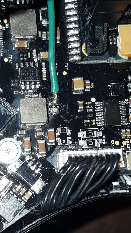
Anyone know what the standard voltage is? It just takes putting a voltmeter black lead on the metal module and the red lead on the black conductors pins until you touch one of the three that bring the "5V" power into the OFDM module. If someone could test that I would be sooo grateful! ")
Thanks anyway. Maybe someone can find the voltage out. I flew a decent distance today but want to make sure I am not under or over powering my transmitter board. I feel confident that it should not shut down because I flew for a while yesterday and then I hovered about 1' off the ground (for safety) when it was at 20% until it did a forced landing at about 7% of battery. The green light on the OFDM was still on and transmitting the whole time. I just want to know if I can up my voltage a bit to get the best out of my transmission signal. I am 90% sure I can go up to about 6 volts but need to be sure. At least it seems to fly as good as ever.
Still no posts about voltage from anyone else. I guess I am going to bump it up to about 5.7v just to keep it strong for the Lightbridge to have as much power as possible. If anyone gets around to testing their drone and finds what the "normal" voltage is please post it here and I will adjust mine to match.
Still no posts about voltage from anyone else. I guess I am going to bump it up to about 5.7v just to keep it strong for the Lightbridge to have as much power as possible. If anyone gets around to testing their drone and finds what the "normal" voltage is please post it here and I will adjust mine to match.
Can you post a pic of what line you need measured? I may swap out a motor tonight, if so I'll do a power line test. Hate to leave ya hanging.
Thank you! It is the voltage at either pin 3, 4 or 10 of this connector. All 3 of those pins are tied together electrically. I found this on another RC forum that shows the layout well.
View media item 2031
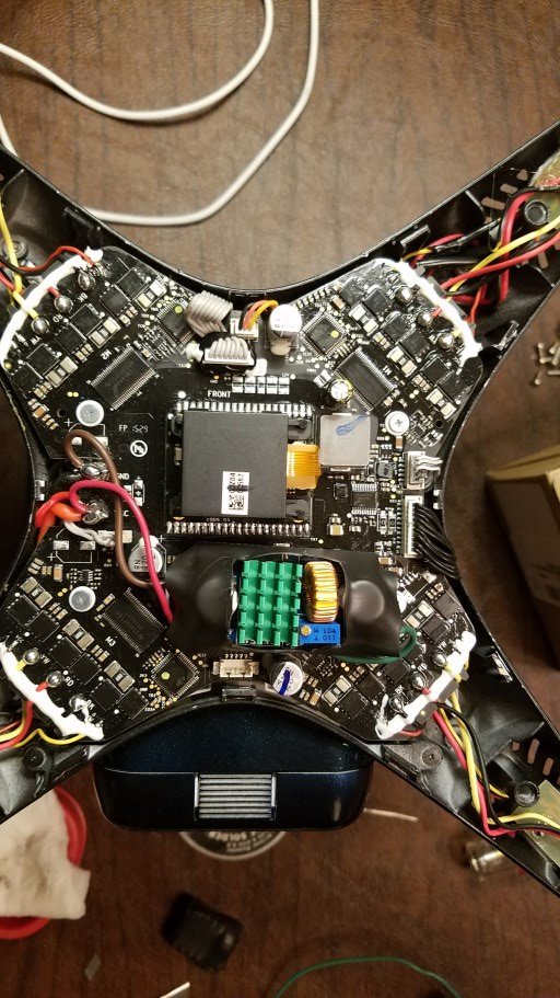
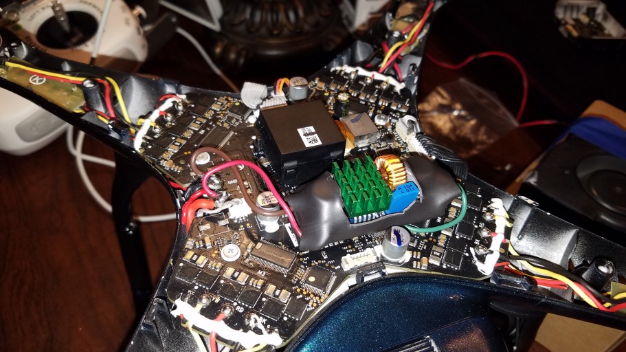
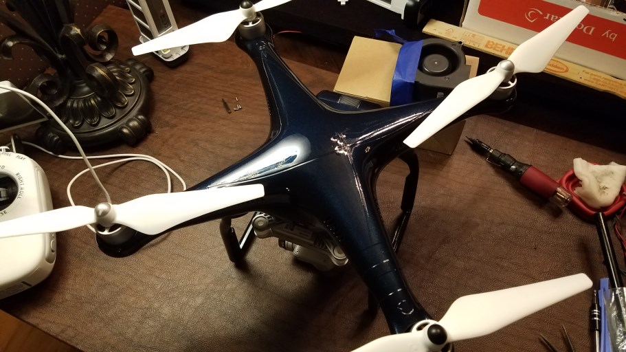
This is a photo of my drone with an adjustable regulator installed. I know it works at 5.2v but I would rather have it set at exactly aht DJI intended. As a former electronic field tech I can say from experience that sometimes a 0.2v difference can stop ghost errors or poor performance.
P.S. Speaking of poor performance. I read a post about a guy who had bad pixilation and 5-6 second video lag. It turns out the heat sink pads in the P3P Gimbal/Video board were not making good contact with the heat sink body. He added some little heat sink pads from Amazon and said his video lag and pixilation is gone. I plan on added those later today when they arrive.
View media item 2031
This is a photo of my drone with an adjustable regulator installed. I know it works at 5.2v but I would rather have it set at exactly aht DJI intended. As a former electronic field tech I can say from experience that sometimes a 0.2v difference can stop ghost errors or poor performance.
P.S. Speaking of poor performance. I read a post about a guy who had bad pixilation and 5-6 second video lag. It turns out the heat sink pads in the P3P Gimbal/Video board were not making good contact with the heat sink body. He added some little heat sink pads from Amazon and said his video lag and pixilation is gone. I plan on added those later today when they arrive.
hi, the subject is old but may be needed by other friends. I have a linkte schema. The 5v line was defective in my device. + the batt line was lit by the capacitor. this section has been cleared. capacitors were added. tps54531 pin3 connected, 12k resistor defective changed. pin3 measured voltage is about 6.7v.


o-gs/dji-hardware-schematics
If my problem is, it is related to the vcc line going to led lere. there is no 12v in front left arm vcc line. front right arm, short circuit from the LED leads (R) to the front left arm vcc line. can these points be measured? Thank you
How can I fix?
esc code : p01012.09 phantom 3 pro
I am glad there is more info than when I was doing mine. I am unsure about what to do about the 12v problems. I lost my P3P last year. If not I would open mine and test a few spots for you.
I actually lost my P3P trying to get some footage of a gas platform explosion last year about 3/4 mile out in a lake. I made the mistake of flying with a battery that had sat for a week and was not reading correct voltage. Learned that lesson fast. I now have a P4P so everything is different inside.
I actually lost my P3P trying to get some footage of a gas platform explosion last year about 3/4 mile out in a lake. I made the mistake of flying with a battery that had sat for a week and was not reading correct voltage. Learned that lesson fast. I now have a P4P so everything is different inside.
I am glad there is more info than when I was doing mine. I am unsure about what to do about the 12v problems. I lost my P3P last year. If not I would open mine and test a few spots for you.
I actually lost my P3P trying to get some footage of a gas platform explosion last year about 3/4 mile out in a lake. I made the mistake of flying with a battery that had sat for a week and was not reading correct voltage. Learned that lesson fast. I now have a P4P so everything is different inside.
Thank you for your interest. I'm sorry for the loss of p3p. The p4 on the way to your table is gratifying. you use hope without any problems.
I do not know english. Google Translate. If there is a typing error, sorry.
If my problem is, it is related to the vcc line going to led lere. there is no 12v in front left arm vcc line. front right arm, short circuit from the LED leads (R) to the front left arm vcc line. can these points be measured?
Can't understand much.. you have issue with interfaces to LEDs?
o-gs/dji-firmware-tools
One of LEDs is not working?
Since VCC seem always connected, LEDs are probably enabled by shorting R/G to GND. There must be a transistor which does that.
Similar threads
- Replies
- 4
- Views
- 4K
- Replies
- 24
- Views
- 13K
- Replies
- 2
- Views
- 1K
- Replies
- 6
- Views
- 5K
- Replies
- 6
- Views
- 2K


Recent Posts
-

-
 North Jersey, Very new old guy trying to get off the ground with a P330Z Phantom 2
- Latest: captainmilehigh
-
-

-
