Ok
Welcome to part 2
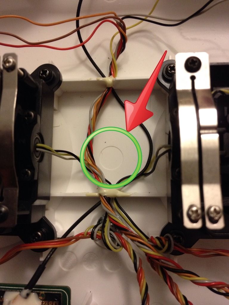
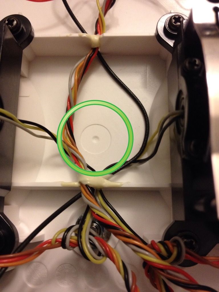
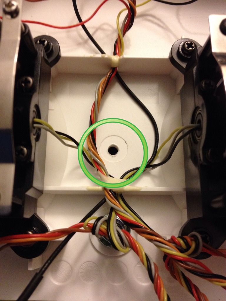
We left off with a pilot hole drilled into Tx, for switch, now we need to drill out hole to the full 7mm required diameter for switch to fit
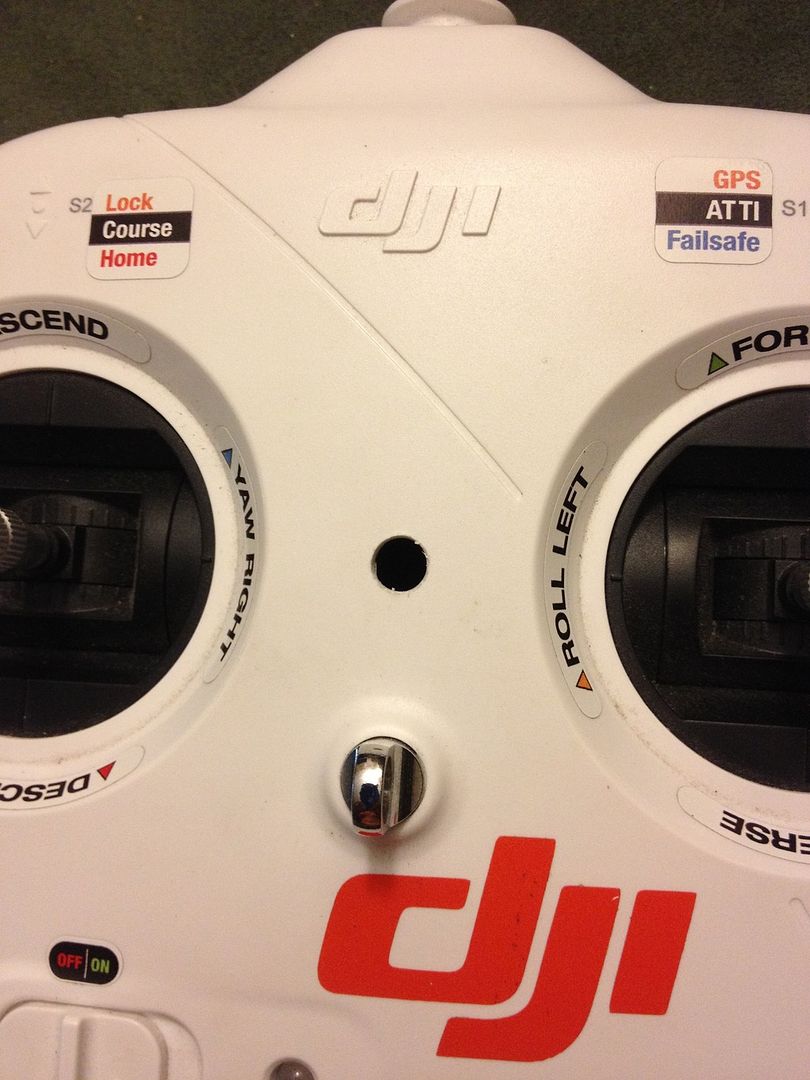
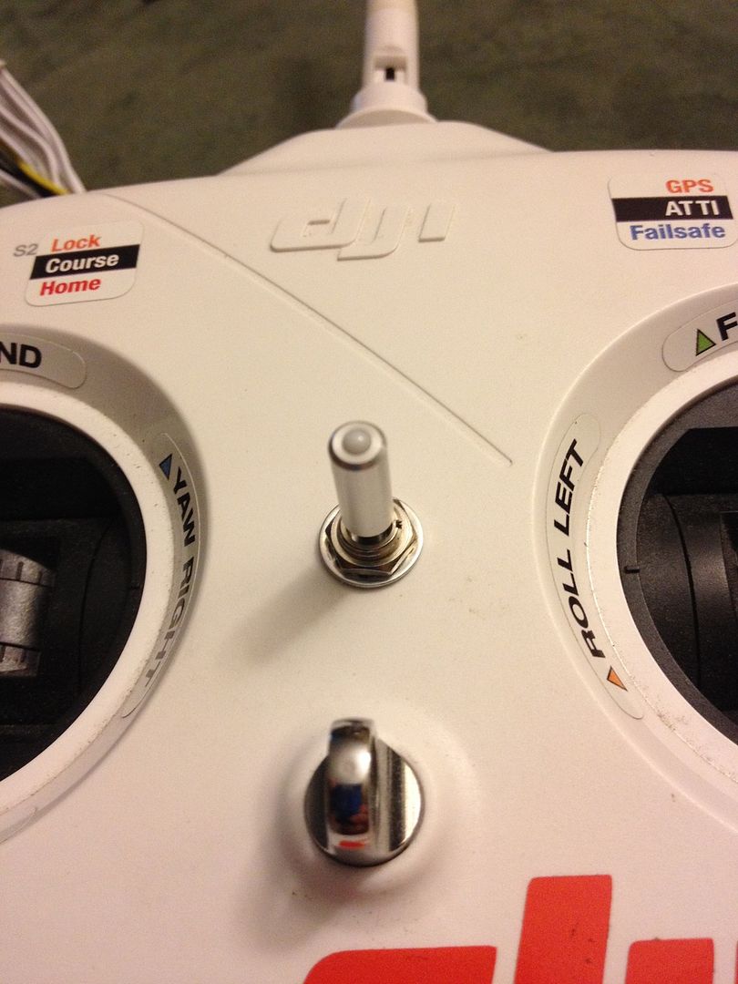
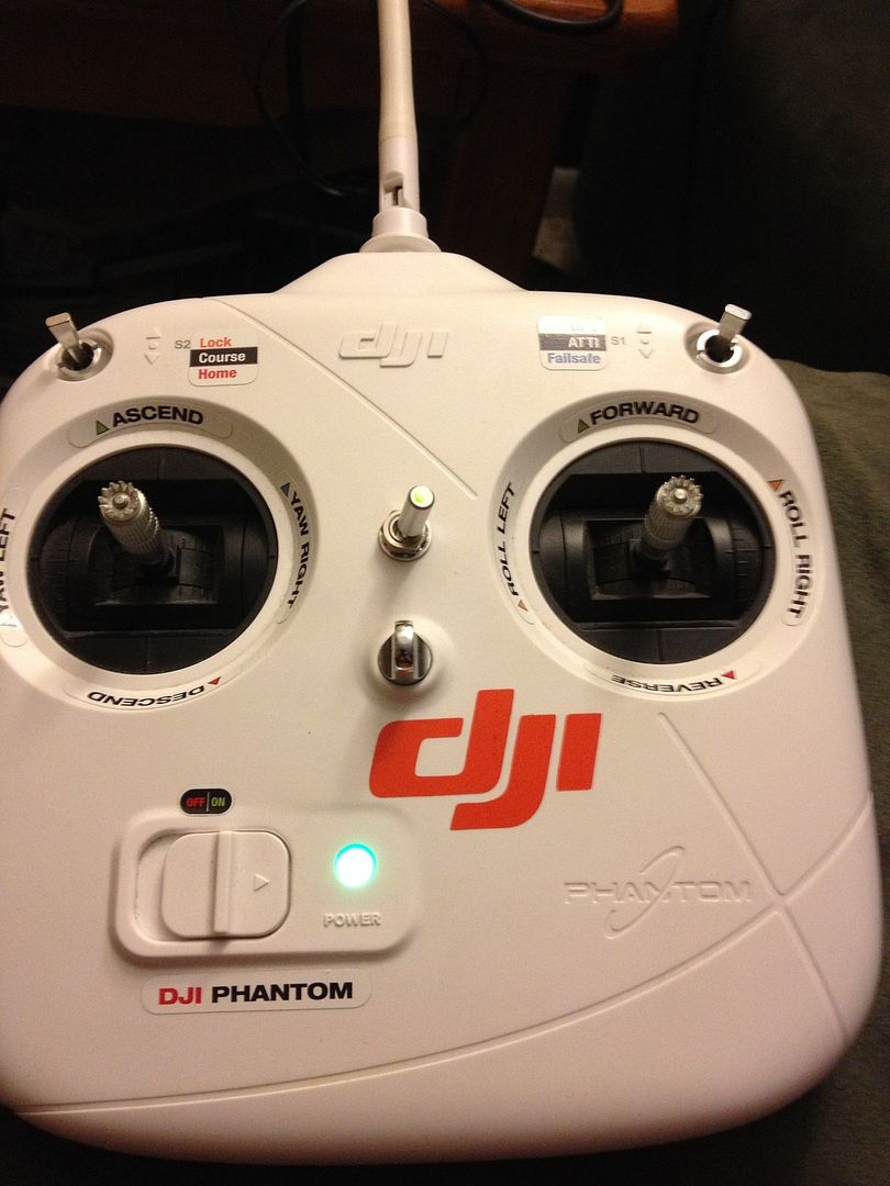
Position switch, whatever orientation, you choose! I chose left to right, left off, center slow, right very slow!
( note, rearrange Tx wires around switch, but keep bundled nicely )
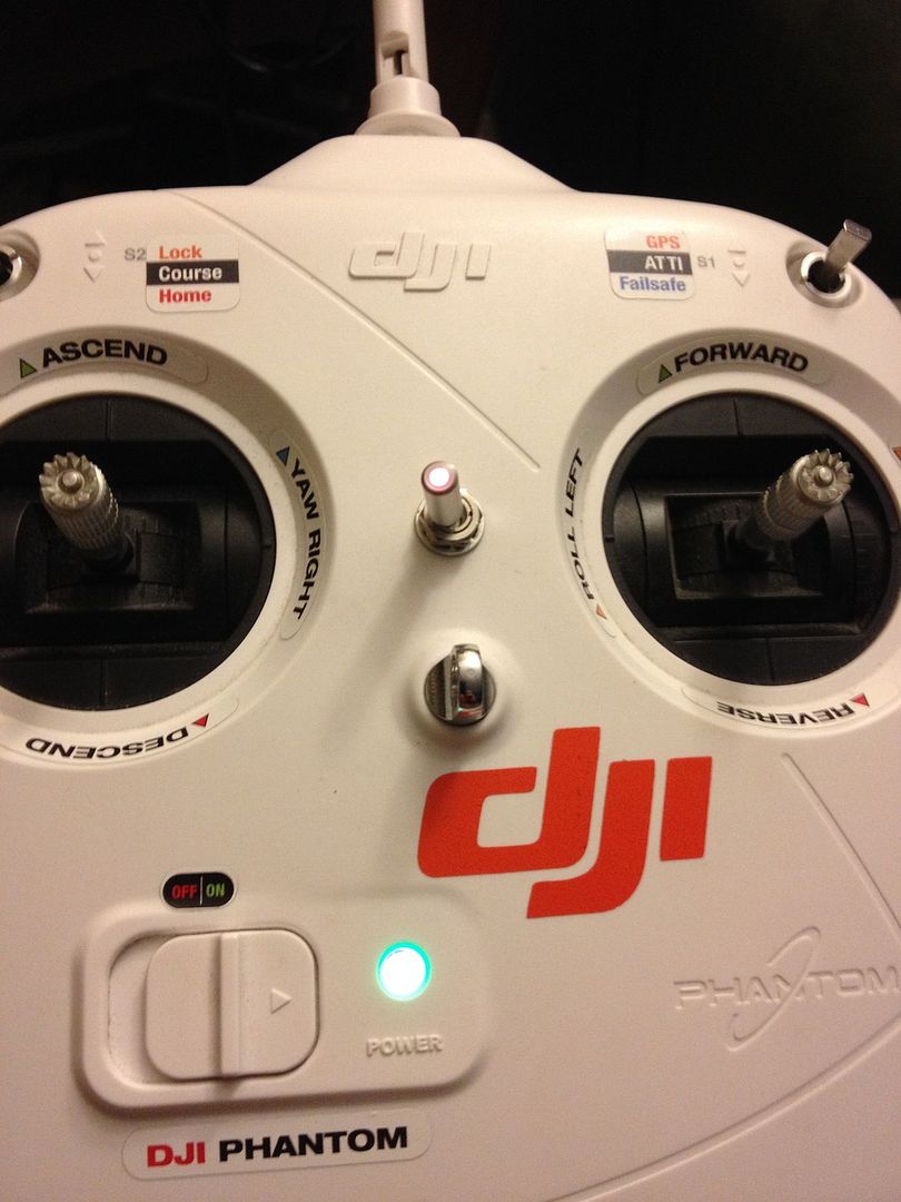
Here is the mounted switch, top side
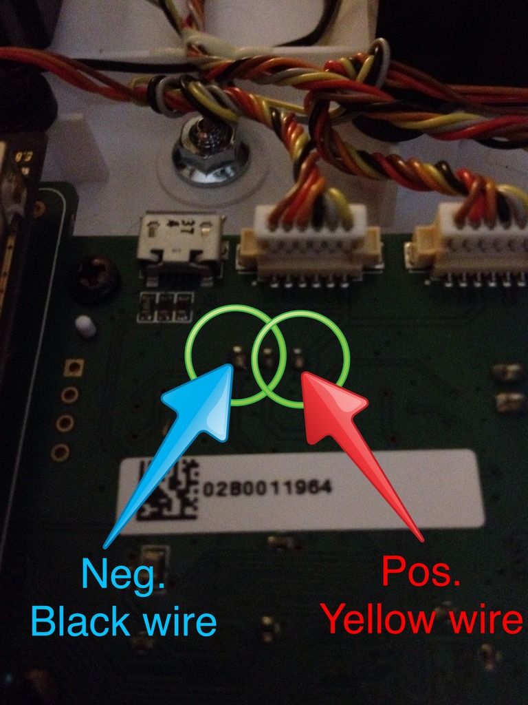
My next task was installing power feed to led in switch ( this is optional, and requires soldering )
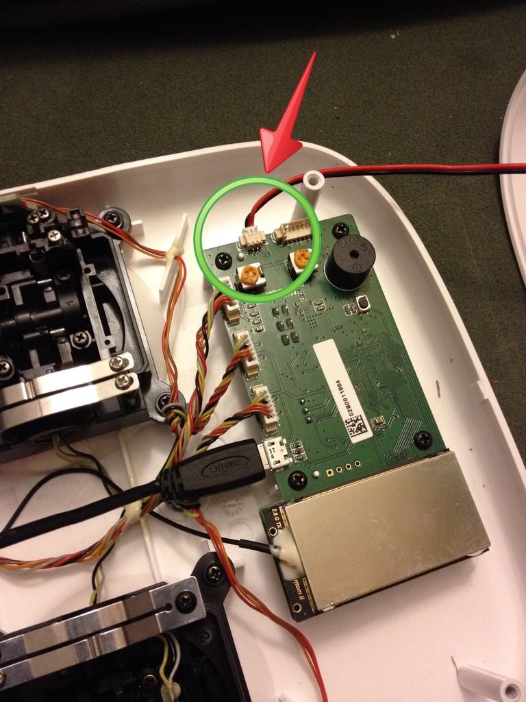
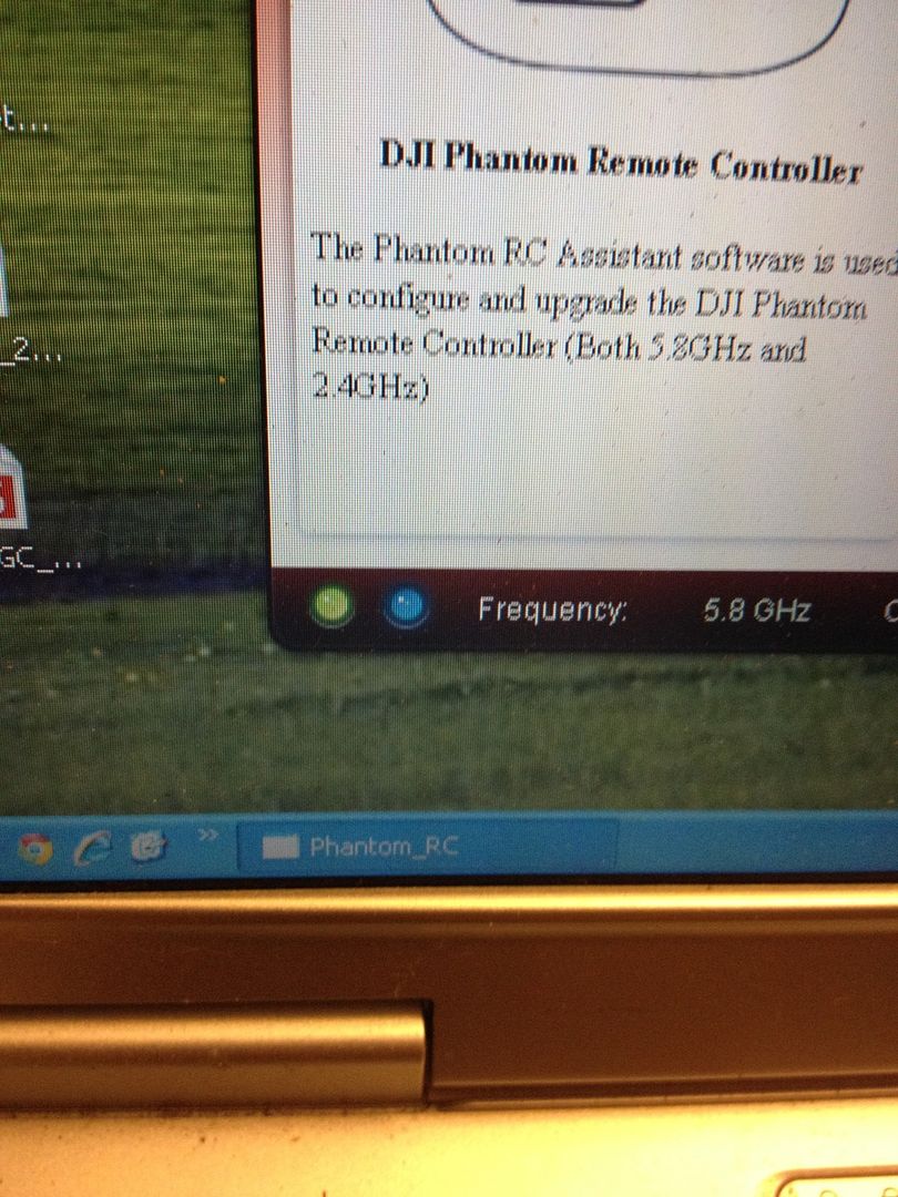
Here is our power source
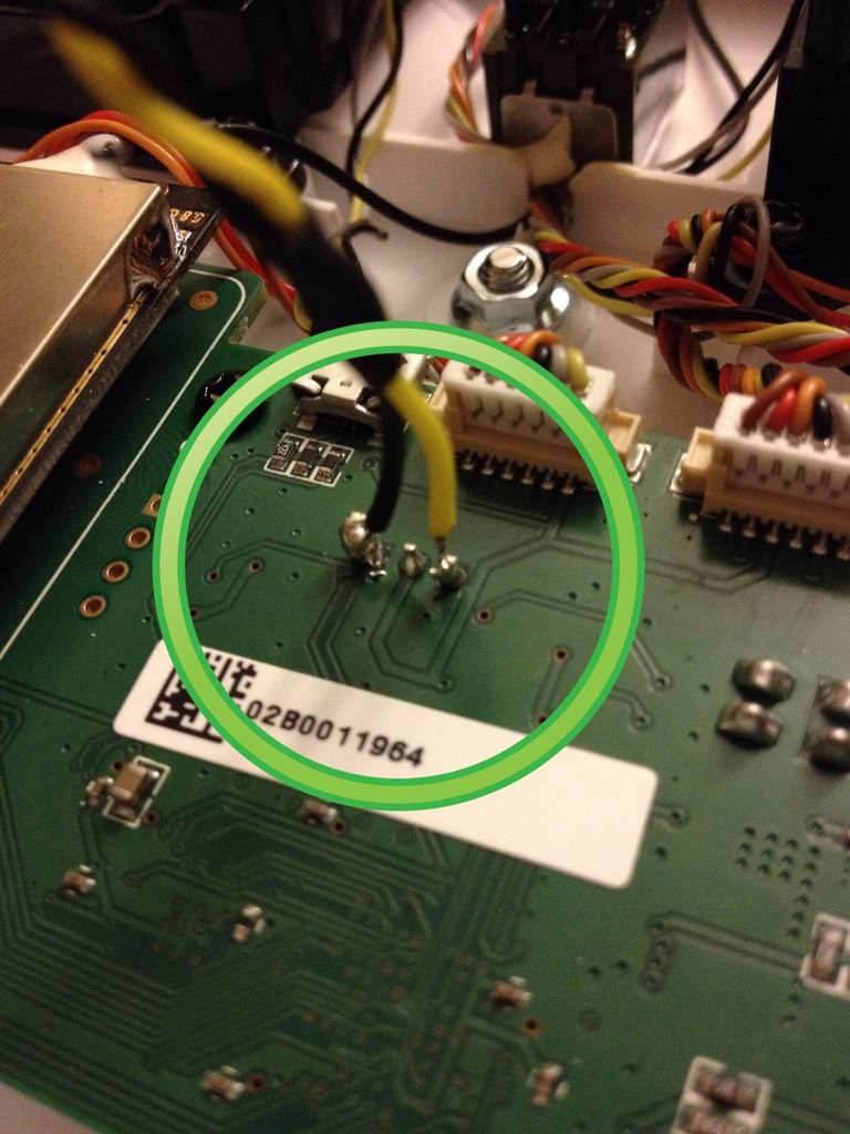
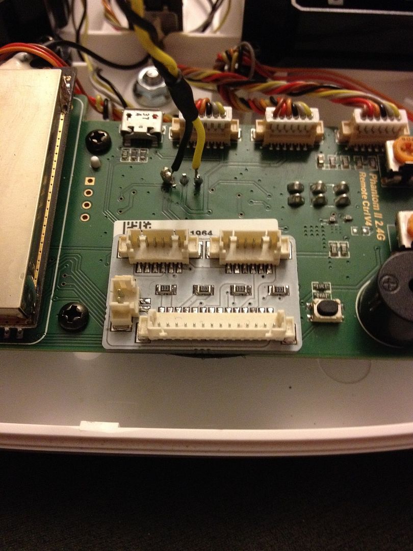
Solder ( Yellow & Black wires ) to board like this
( note: center pin is not touched )
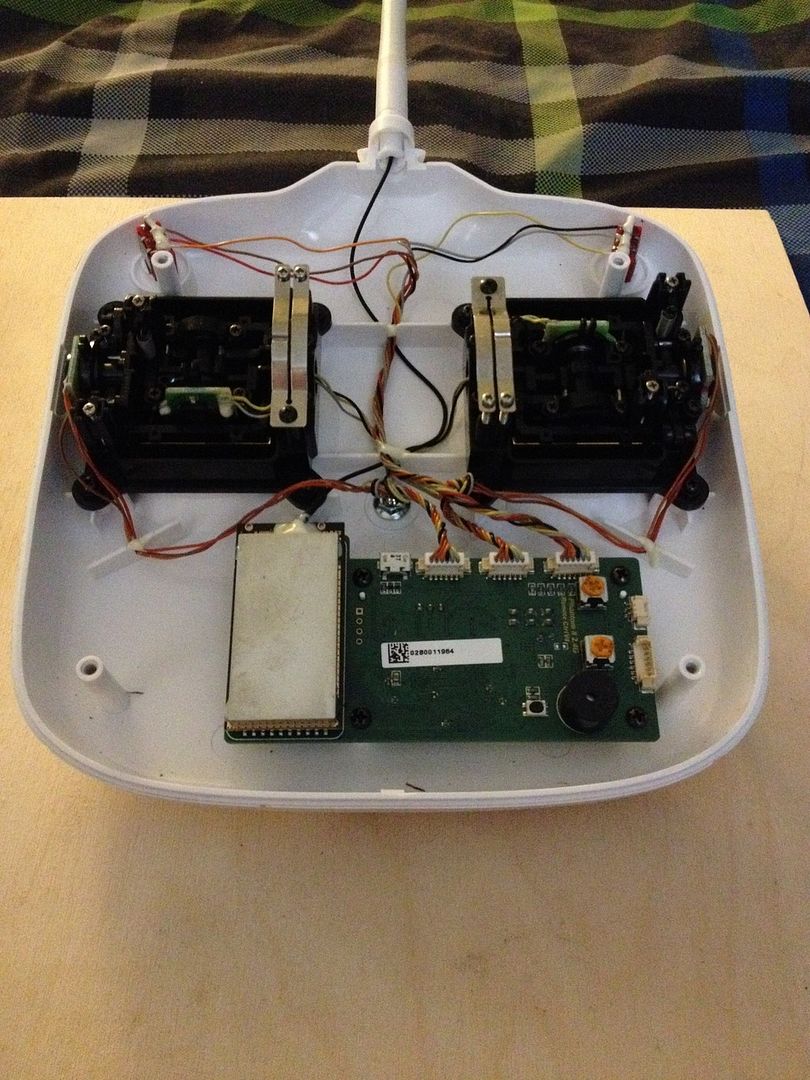
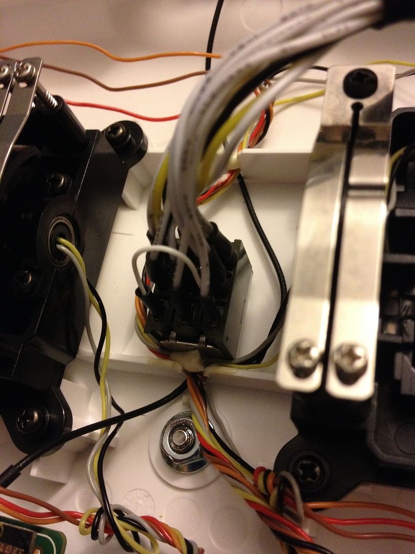
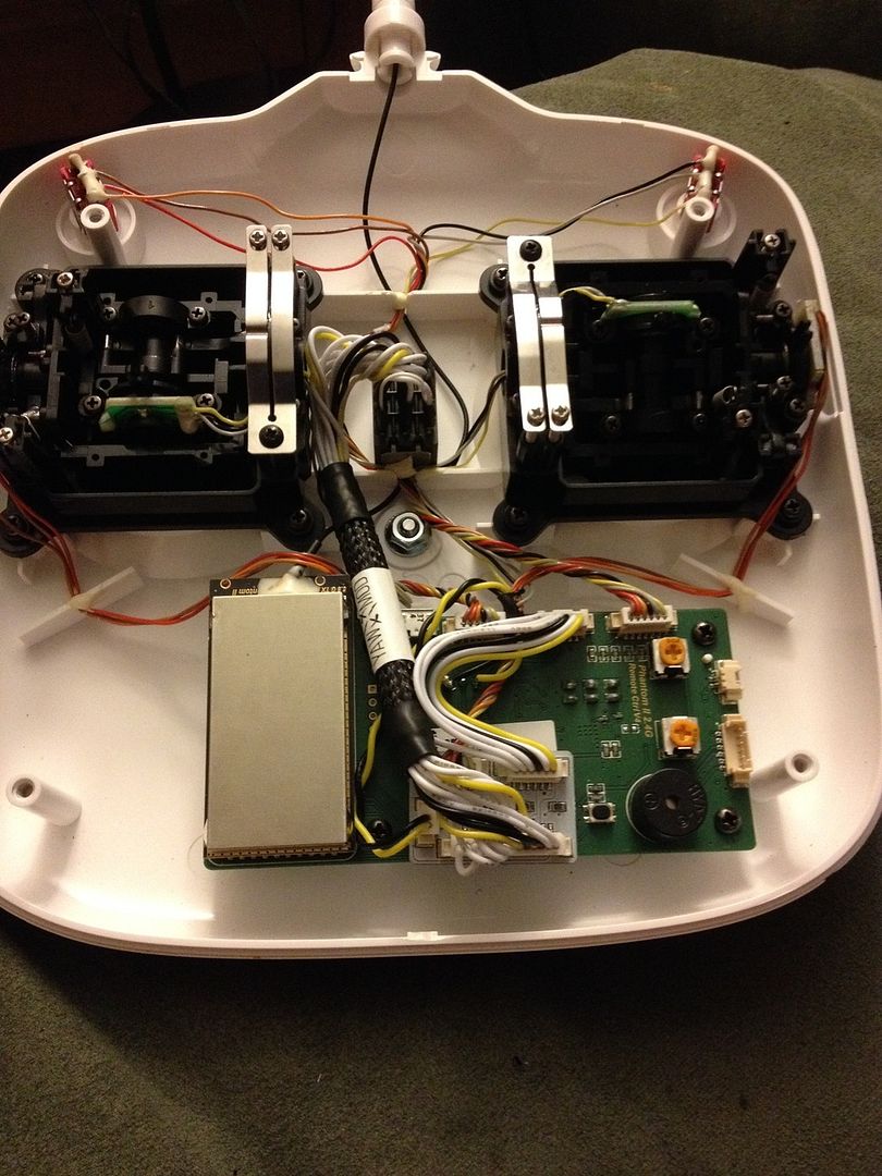
Now that the dirty work is done, let's put it all together, we will start with mini PC board install
( I used Velcro, as I ultimately want to swap back and forth with my dial wheel Tx )
Place board here
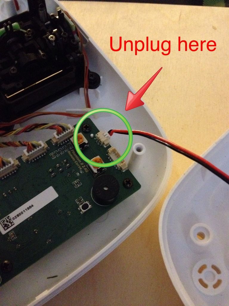
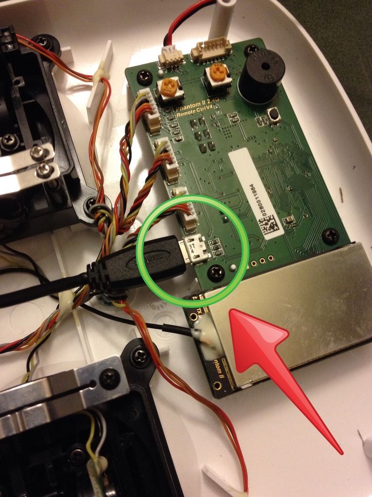
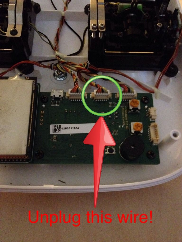
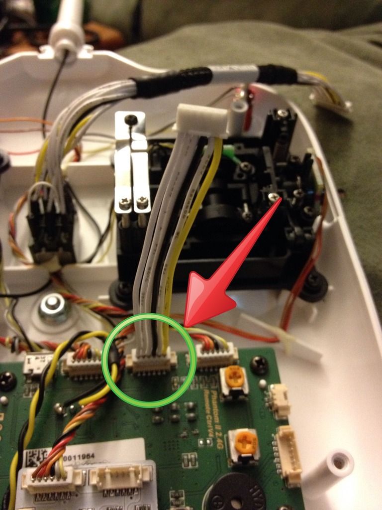
Now we need this plug
Unplug it
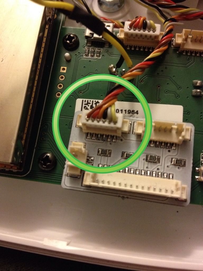
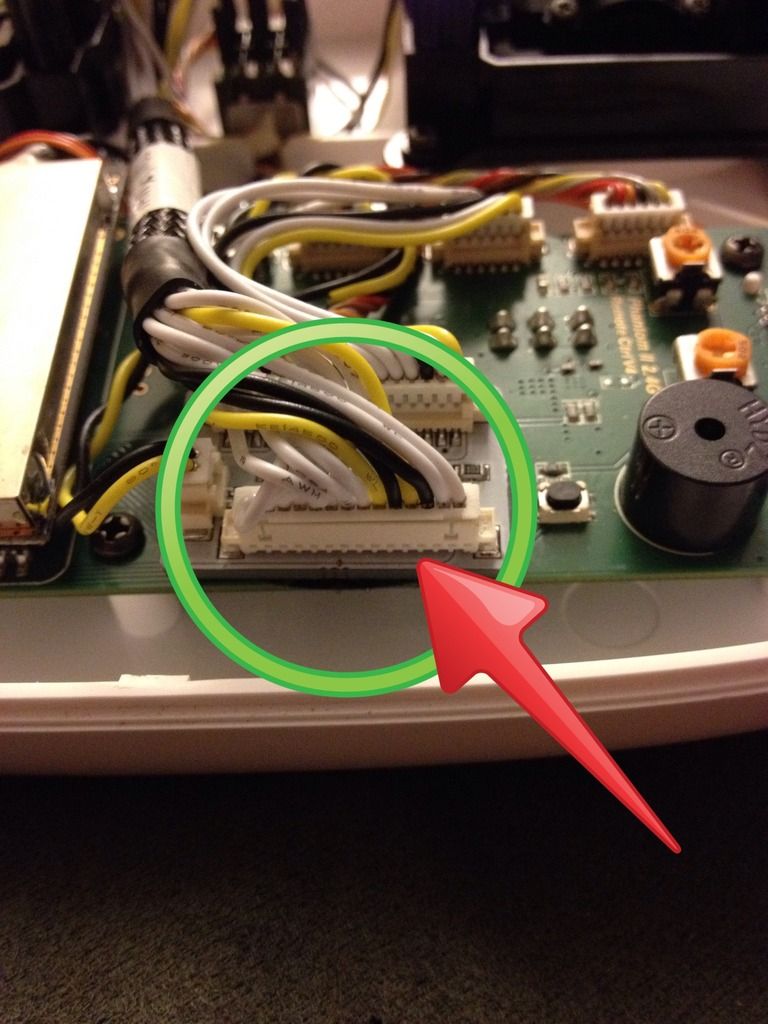
Plug that plug to mini PC board here
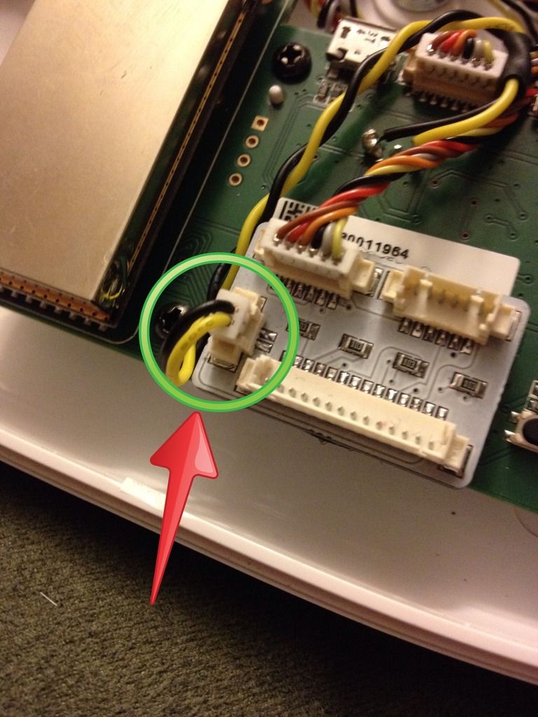
Now let's plug in the power led wire, the ( Yellow & Black one ) plug it to mini PC board here
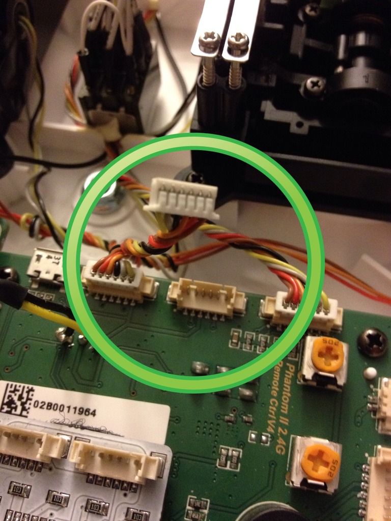
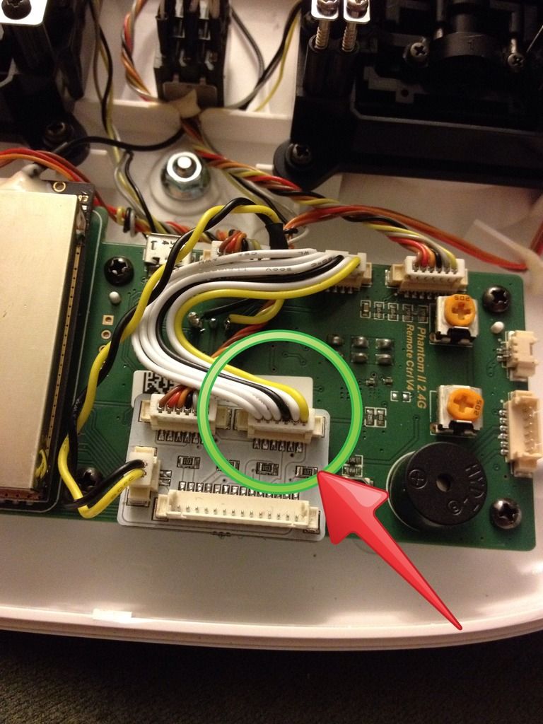
Now plug the multi colored jumper wire to Tx board here
Plug other end to mini PC board here
Now plug the switch plug to mini PC board here ( last plug )
When done, should look something like this
( nice and neat )
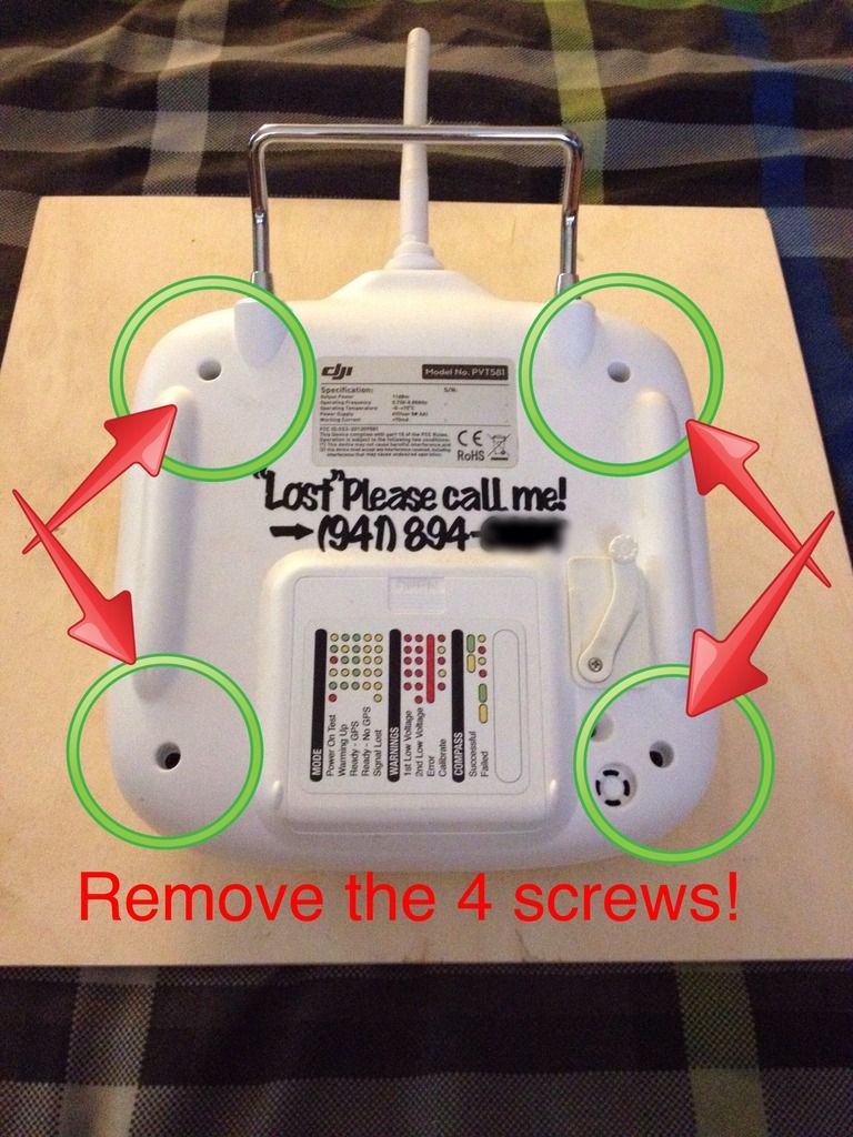
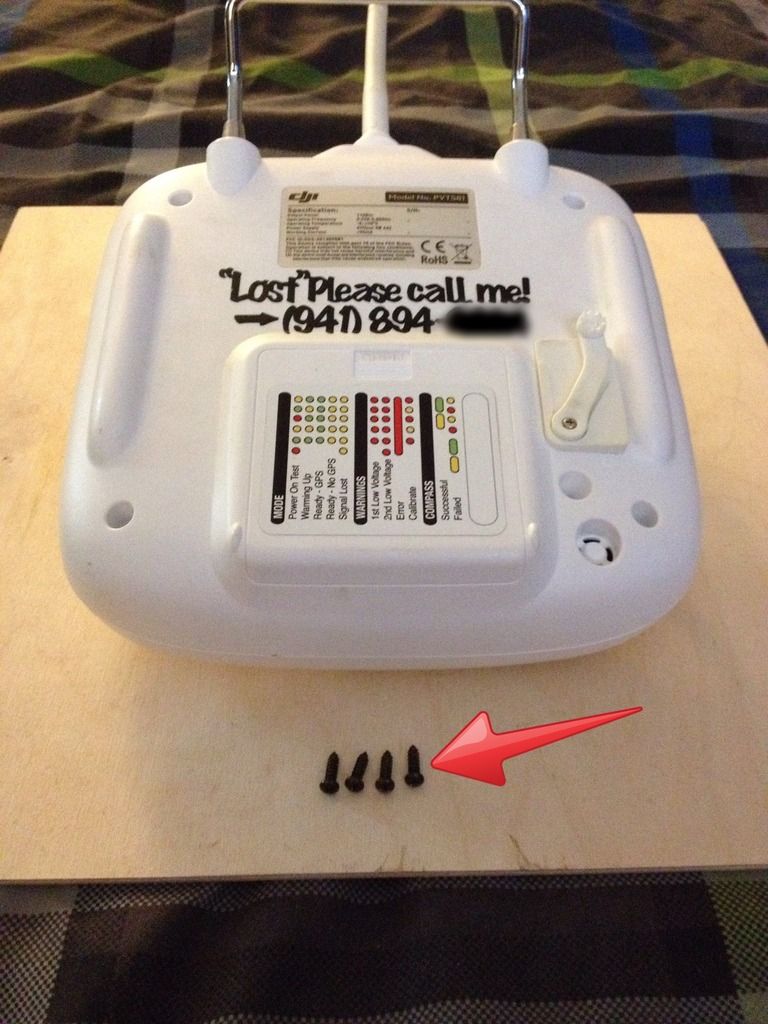
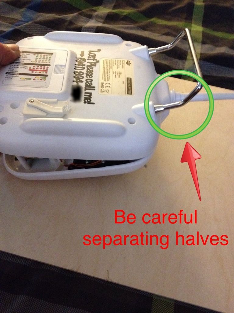
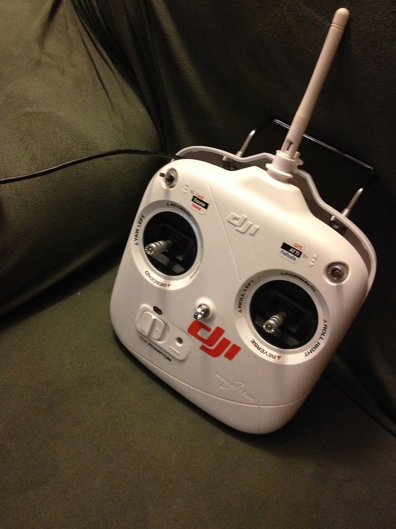
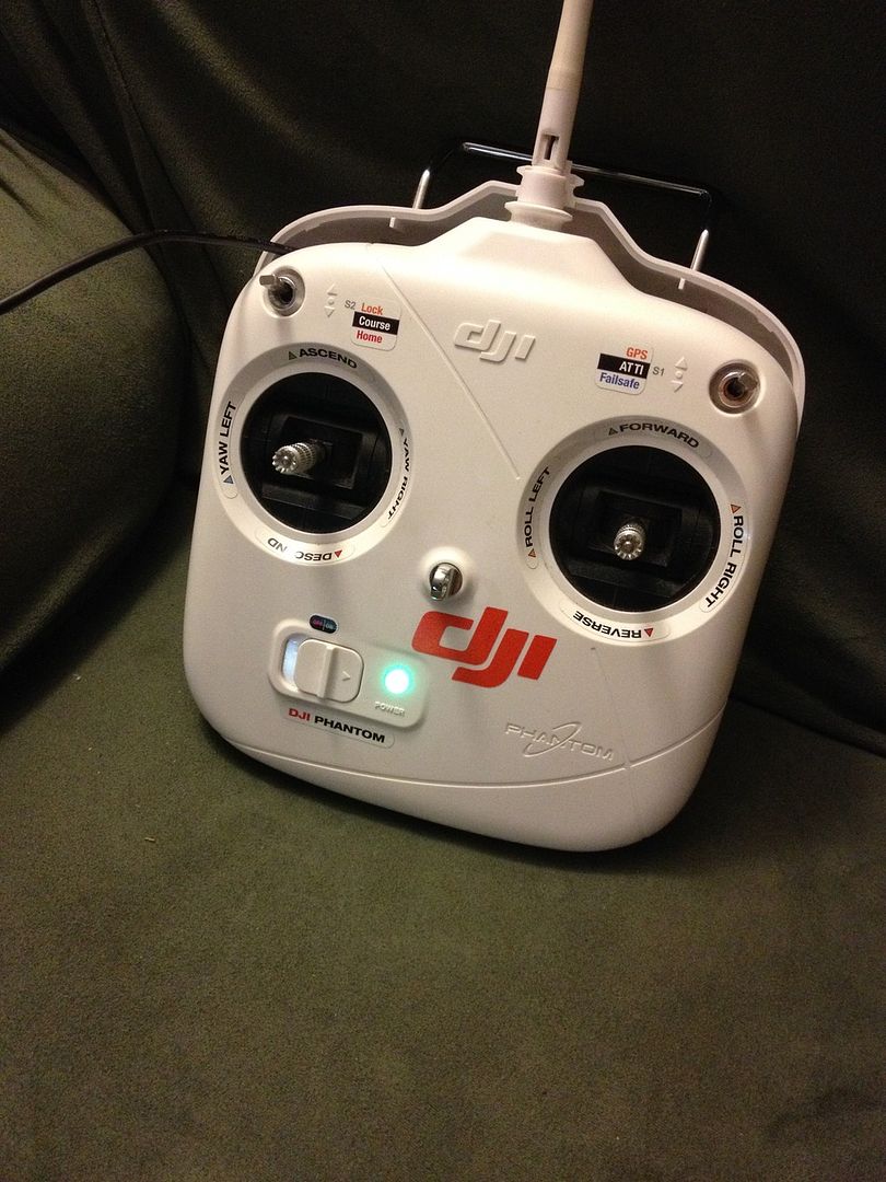
Ok, carefully put Tx halves back together, then turn on Tx, see if switch works
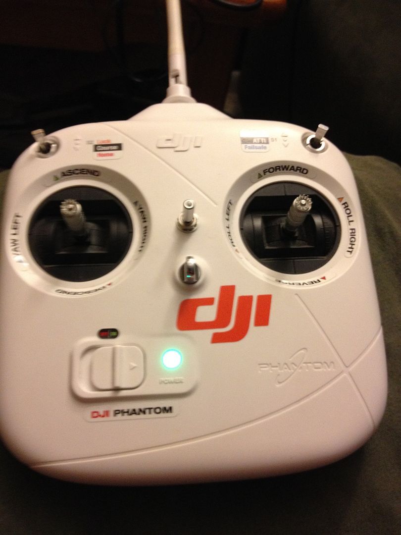
Mine is left OFF ( red led )
Middle slow ( no light )
And finally right very slow ( green led )
Ok, that is it,
Will update, when weather allows me to actually test it all out! Thanks again
( Fyod ).
Take care, Fly safe!
J Dot


")

")