Ive recently crashed my p3 standard, aftrr crashing i had to replace the yaw arm on thr camera, the ribbon cable and also 2 motors. Unfortunantley the 2 motors i have replaced are not working either. I replaced both motors on one side of the p3 and when i turn it on it does nothing on that side. I swapped the good motor over the that side that wasnt working and it worked fine so i guessed no mother board damaged on that side put the bad motor on the good side and nothing. Hooked the new motor on the good side that was origanlly working after the crash and it doesnt work either. Can some one help amd give me some insight of what may be going on


You are using an out of date browser. It may not display this or other websites correctly.
You should upgrade or use an alternative browser.
You should upgrade or use an alternative browser.
Motor problem
- Thread starter Rva1980
- Start date
What do you mean?Are you terminating the motor fly leads at the mainboard?
Are you attempting the make the electrical connections at the main board (I.e as originally performed) or are you trying to cut and terminate somewhere along the run from the board to motor. Your explanation of the problem suggests the most likely issue is with your workmanship.What do you mean?
Did you remove the insulation from the individual strands on the fly leads (solder bath immersion or scraping off). The fly leads are magnet wire (extensions of the motor windings) and each strand is individually insukated. They can be spliced but its a more complicated procedure than soldering directly to the main board with a much higher probability of poor performance and/or failure in service.I did originally cut and splice the new motor wires to the existing mother board wires that were there already. But i made sure all contact is good
When i removed the good motor that was already working, i heated up the solder from the main board and moved it to the bad side resoldered it right back and it worked with no problem on the side that originally that stopped working after the crash. Under the insulation of the wire leads on from the motor there are 2 seperate wires on each colored wire
Yes... two individually insulated solid core conductors within each sheath (the motor has 3 groups of four poles series wound).When i removed the good motor that was already working, i heated up the solder from the main board and moved it to the bad side resoldered it right back and it worked with no problem on the side that originally that stopped working after the crash. Under the insulation of the wire leads on from the motor there are 2 seperate wires on each colored wire
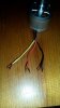
That doesn't look right- the leads should be longer with pre tinned ends (assuming these have been cut). You need to scrape all the clear insulation back to bare wire tin and sweat to whatever length you need to reach the main board and terminate at the main board. Whatever is within each sheath needs to be taken back to the corresponding labelled connection at the mainboard.
Im sorry, i am new to all this. Im not understanding what you mean. New, yes the leads were longer i cant remember what then ends looked like as i had cut them off and threw them away. I hope this wasnt a big mistake on my part. Ughh
I'm sorry I can't think of another way to explain it. The mainboard termination points are labelled so you know which colour (the motor fly leads) connect to which solder pad on the PCB. All of the individualy insulated copper wires within each sheath as they leave the motor need to be terminated to the corresponding solder pad on the mainboard. It is a largely trivial excersize with basic soldering competence however you do need to be particularly thorough in removing the insulation prior to tinning. I frequently terminate magnet wire connections and use a molten solder bath to remove insulation and tin in one operation. If you insist on proceeding with splicing the wires make sure you use an appropriate diameter heat shrink to insulate and provide mechanical stability to the joint.Im sorry, i am new to all this. Im not understanding what you mean. New, yes the leads were longer i cant remember what then ends looked like as i had cut them off and threw them away. I hope this wasnt a big mistake on my part. Ughh
In other words, the wires under the colored plastic insulation are enamel coated and has to be scraped off in order to be able to make a solid electrical connection.

You can take it from here Mate ;--)In other words, the wires under the colored plastic insulation are enamel coated and has to be scraped off in order to be able to make a solid electrical connection.
Oh ok, so the wires with in the colored sheeth are also insulated as well and them to make good solid connection they also have to be cleaned of the coating it has. I will try to clean and re-solder them and i hope this will fix the problem. I should have never cut the ends of the 2 new motors and try to splice together is what is boils down to. Stupid me
We got there..... use a razor blade to meticulously remove the insulation and generously tin each strand with a hot iron prior to sweating together. If the solder beads or drips off you know you have done a less than satisfactory job of removing the coating (apply the solder to the wire and not the iron tip).Oh ok, so the wires with in the colored sheeth are also insulated as well and them to make good solid connection they also have to be cleaned of the coating it has. I will try to clean and re-solder them and i hope this will fix the problem. I should have never cut the ends of the 2 new motors and try to splice together is what is boils down to. Stupid me
RVA1980:In other words, the wires under the colored plastic insulation are enamel coated and has to be scraped off in order to be able to make a solid electrical connection.
Until this post I understand why you were in the dark. I am an electrical engineer and knew what was up, but I can see how you were confused. Good luck. Let us know how you make out.
Thanks for all the advice guys... i used a razor to clean all the clear resin off of the motor wite leads, soldered them all back togther and they worked. Now i have to finish putting all back together and see if it will actually fly. One thing i did notice is after putting tbe motors back on and taking it outside to see if they will spin so i could get gps signal. I do have the propellers off, when i use the auto take off button the motors spin for a few seconds then stop. Is this suppose to happen? Normally with the the thing together auto take up they stay spinning to keep the quad up. Are they going to stop like this in mid air once all put back together? Can some one give me some insight on this issue please
Similar threads
- Replies
- 4
- Views
- 2K
- Replies
- 31
- Views
- 18K
- Replies
- 2
- Views
- 2K
- Replies
- 6
- Views
- 5K


