Installing iosd mini/pmu in Phantom V1.2

Joined
May 15, 2014
Messages
675
Reaction score
8
Age
74
Location
Tionesta, California
I am trying to install the iosd mini with pmu v2 into my phantom v1.2 and I wonder about these connections labled x1 x2 x3 on the Naza M device. When I opened it up there is a 3 wire connector leading to the main board from the x3 slot. There was the same set up in X2 that leads to the board that has the antenna. Now on the pmu there is a connector that says X3 and some other stuff that looks like voltage, can those be plugged into any of those 3 slots? Then there is the slot labled U still under the EXP main heading, what are the uses of that slot. I read the pmu manual and I start to get a headache so any help or pointers on where to look is appreciated.
 
The X3 cable on the PMU connects to X3 on the NAZA, replacing the one from the mainboard to that port (the PMU you bought takes the place of the one built in to the mainboard).

The cable from the receiver should stay connected to X2 in the NAZA. The X1 port isn't used unless you need to control tilt on a gimbal.

The thick red and black leads on the PMU need to be connected to power in the Phantom, the best way is usually to just solder them on at the same points the main lead from the battery attaches to the board.

The U port on the NAZA is only needed if you're connecting to an aftermarket receiver via "traditional" setup....i.e. a separate cable for each channel instead of the single-cable method you're using now.
 
Ok, I am starting to get it. The receiver is the board that has the antenna, stays plugged into x2, I remove the current line going into x3 and tuck it someplace safe as it is no longer used. I plug the line labled x3 from the pmu into the x3 on Naza m. I provide power by soldering the power cables to where the battery connects to the main board. Gps comes out of Naza and into pmu the line labled "exp" goes into gps on the Naza m and that is it. I will see if I need to upgrade firmware as indicated in the pmu instruction manual. thanks for the help Ol Photography.

And I wish to report it works GREAT. I love it. I will see if I can document this experience for others who might wish to have iosd on a phantom v1.2 using fatshark camera and cannot find the answers in one place otherwise.
 
Sounds like you have it all sorted just right! I know it's a little odd because using the PMU in a Phantom was sort of an ad-hoc solution before they released the upgrade board and shortly thereafter the P2.
 
I would still be sitting here scratching my head if you had not explained x3..thanks. Here is a pic of the lead going to x3 and I think I might notch my upper shell and hang the pmu out on the side. Does this sound like a good idea. I have heard there are concerns about the pmu and the mini iosd heating up without good airflow
 

Attachments

  • 20140719_141656.jpeg
    20140719_141656.jpeg
    65.8 KB · Views: 704
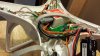
If anyone is thinking of doing this mod here is the process I used to connect the mini iosd video cable to my existing fatshark camera cable. I open up the shielding on the cable that goes from the camera to the fatshark transmitter. There are 3 wires inside mine. 1 red wire which I understand is power, 1 white wire which is the video cable and a black wire there was an unshielded twist of steel cable that was the ground or black wire (it is black at both ends where it attaches to connectors, but inside my shielded wrap of this cable the ground is bare)

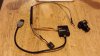
From the mini iosd my cable has 4 wires brown, orange, brown, yellow and were it plugs into the mini iosd the first is gnd and that is a brown wire, I combinded both brown wires into one and soldered them to the ground wire that I had exposed when I removed the shielding from the cable from camera to transmitter. So now both brown wires are addressed, the next is the orange wire which is labled video out. At this point I cut the white wire and on the end going to the transmitter I solder the orange wire. The yellow wire, the last one, I solder to the white wire going to the camera. I recommend you slide litte shrink wrap tubes onto the white wire prior to soldering and then pull up and shrink wrap the wire wires professionally. On the brown wires where it was soldered to the ground wire, clean up nicely with electrical tape. I then shrink wrapped the whole assembly, I built it so that the ends that connect to the mini iosd and to the transmitter were the same length, you might want to consider having a different length for your assembly.
 

Attachments

  • 20140719_100534.jpeg
    20140719_100534.jpeg
    64.7 KB · Views: 700
This evening I was showing my grandkids the fatshark goggles and my 7" monitor and I said to my granddaughter that I forgot my phone so I wont be able to fly for too long as I don't know the battery state. I had been flying watching the bird while they all looked at the screens. My grand daughter said, its ok, there is your battery and she pointed to my battery on the screen.. Ever since I started I flying I have not liked not knowing my current battery state. Now I know that and a bunch of stuff. I am extremely happy with fpv. It is nice to take people as a passenger in my flying machine.
 

Recent Posts

Members online

No members online now.

Forum statistics

Threads
143,094
Messages
1,467,602
Members
104,980
Latest member
ozmtl