

You are using an out of date browser. It may not display this or other websites correctly.
You should upgrade or use an alternative browser.
You should upgrade or use an alternative browser.
Improved GPS reception?
- Thread starter Geeber
- Start date
- Joined
- May 10, 2014
- Messages
- 3,012
- Reaction score
- 522
M.Tigelaar said:Did you read the text on YouTube?robinb said:Which was which ?
There is NO text
N017RW
Premium Pilot
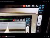
This is what I saw for text (cut/paste):
Published on Aug 21, 2014
The white ipad mini have the mod with turned cable and foil on the cable and foil all over the GPS.
The black ipad have only the turned cable and foil on the cable.
Published on Aug 21, 2014
The white ipad mini have the mod with turned cable and foil on the cable and foil all over the GPS.
The black ipad have only the turned cable and foil on the cable.
Yep thats it. :mrgreen:
I have an other vision plus without GPS mod, so I can test it with the other two.
Then we now it all")
I have an other vision plus without GPS mod, so I can test it with the other two.
Then we now it all
http://youtu.be/yIY4WCfZUoErobinb said:yes but the video only shows a white iPad
I see two ipad's :|
Attachments
N017RW
Premium Pilot
Not much Mori, but it is still beter then only turning the cable and put the rest of the cable in aluminium foil.Mori55 said:So the white with the full mod is better.
I wil test also the difference between the standard vision without mod and the black one with the half mod.
FYI with foil mod that covers the factory shield and the cable across it, I got 10 sats in < 30 seconds on the ground and 13 sats in the air last night!!! At first I didnt think it made an improvement because on my first test I couldnt tell. But on my second test the next day, I did notice an improvement. I did NOT have problems prior (such as not enough sats or sats dropping with camera on) but I did the mod cause I didnt think it would hurt anything. No extra heat detected either. I'm lovin it.
Well said.M.Tigelaar said:You can never receive enough satellites :mrgreen: :mrgreen:
I cannot understand the way the shielding is done inside the phantom and the tutorials. I develop electronic circuits and boards and far as I understand principles of electronic a shield always has to be grounded to work properly. There is already a proper shield on top of the gps which is not grounded. Why not? The only reason why i would not do this is because the gray clay could be pressed into a soldering point/component and the copper foil of the shield could cause damages.
I would not apply a second, ungrounded shield, I would put an isolation layer between existing shield and gps board and then connect existing shield to ground.
Also why shielding the cable? The cable should only carry nmea sentences via rs232 and would not be responsible for receiving any signal.
I got some gps antennas with amplifier laying around here I want to test as well, this weak gps reception sucks indeed...
I will start testing this afternoon...

N017RW
Premium Pilot
criopt said:I cannot understand the way the shielding is done inside the phantom and the tutorials. I develop electronic circuits and boards and far as I understand principles of electronic a shield always has to be grounded to work properly. There is already a proper shield on top of the gps which is not grounded. Why not? The only reason why i would not do this is because the gray clay could be pressed into a soldering point/component and the copper foil of the shield could cause damages.
I would not apply a second, ungrounded shield, I would put an isolation layer between existing shield and gps board and then connect existing shield to ground.
Also why shielding the cable? The cable should only carry nmea sentences via rs232 and would not be responsible for receiving any signal.
I got some gps antennas with amplifier laying around here I want to test as well, this weak gps reception sucks indeed...
I will start testing this afternoon...
EMI supression is a science and often can seem counterintuitive.
An ungrounded screen/shield will still substantially attenuate higher frequency signals because of the low-pass filter formed by its resistance, distributed shunt capacitance, and series inductance.
Comm. cables act as antennas both [possibly] radiating and coupling energy to places that are undesired. You've seen those cylinder shaped items on the end of computer peripheral cables?... those are chokes designed to prevent the cable from acting like radiating or receiving antennas and coupling EMI into equipment.
Not sure it is RS232 on that cable, you can find some info here:
http://www.rcgroups.com/forums/showthread.php?t=1995704
It seems that due to cost (or ???) DJI or the GPS board vendor chose not to employ adequate interference rejection into thier design.
If you are interested you can Google the "uBlox NEO-6Q", which is the GPS engine contained in the Phantoms, for more information on them.
Really doesn't matter what the cable carries for signal or if its digital or analog. You can still get RF on it.
Sure, but in our case RF can only cause dropouts in communication between the modules, means bit words get invalid or unreadable. No way it influences sat signal reception. (Unless its not infusing vcc from gps module which would lower SNR of course) Anyway, testing is always better than too much theory so back to the workbench....rrmccabe said:Really doesn't matter what the cable carries for signal or if its digital or analog. You can still get RF on it.
- Joined
- Apr 17, 2014
- Messages
- 692
- Reaction score
- 4
sweet.. but also recognize that satellite reception can vary not only day to day, but hour to hour. See this site: http://satpredictor.navcomtech.comBlackTracer said:FYI with foil mod that covers the factory shield and the cable across it, I got 10 sats in < 30 seconds on the ground and 13 sats in the air last night!!! At first I didnt think it made an improvement because on my first test I couldnt tell. But on my second test the next day, I did notice an improvement. I did NOT have problems prior (such as not enough sats or sats dropping with camera on) but I did the mod cause I didnt think it would hurt anything. No extra heat detected either. I'm lovin it.
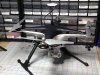
Just throwing this out there, but you could always do what I did and purchase a combined GPS/Compass from a Naza "Lite" and mount it externally. It's 100% compatible and there's simply no interference this way. Just remove the internal GPS and plug in the puck. The assistant may ask for an IMU calibration, but after that it's all smooth sailing.
GPS locks are fast, tight and stable, and the compass works beautifully. As you can see, I have an aftermarket landing gear which I modified to fit a P2V+, but there's no need to worry about compass mounting on the leg because it's all part of the combined GPS unit.
I went the elaborate route by snipping off the stock molex on the puck's cable, shortened it, and ran it through a grommet in the rear of the top shell, and then soldered on a new molex. That's much more elaborate than necessary though, as one could simply make a small cutout in the top shell and use the entire stock, intact cable without modification.
On the vision (original) there's only the one GPS port. On the Vision+ there are separate compass and GPS ports, but the GPS port still accepts compass signals through the GPS port, so it works fine on either flavor and probably works fine on a non vision as well.
Naza GPS/Compass Puck $100: http://www.banggood.com/DJI-NAZA-Lite-V ... 86239.html
Tarot GPS mount (works well on the curved surface because there's only one mounting point): http://www.banggood.com/Tarot-680-Pro-T ... 34829.html
Attachments
Similar threads
- Replies
- 4
- Views
- 977
- Replies
- 2
- Views
- 656
- Replies
- 0
- Views
- 573


