Phantom 4 pro Gimbal ESC board calibration help

Joined
Mar 12, 2021
Messages
12
Reaction score
3
Age
49
Hi to all of you, drone enthusiasts,

I come again here on the forum hoping that someone has experience with ESC Board calibration.
I have a P4PRO drone which had the so called "limp gimbal" sindrome and after we unscuccesfully try everything to correct it (gimbal calibration, imu calibration,firmware downgrade, firmware update, etc) we have come to the conclusion that the gimbal esc board is dead and needs replacement.

So, I bought one from ebay and replace it, but now we have another problem: the camera YAW direction is not straight, but facing to the left about 45 degres. I noticed that the ebay seller posted on his page that the ESC board needs professional calibration after replacing.

Now I come to you with the question: does anyone have any ideea of how this calibration is performed ?
We find some clues on github.com about the "dji-firmware-tools", and on another site: wiki.dji-rev.com about OGs Service Tool for Dji products

Does anyone try such calibration with some of these software ? Is this calibration need the specific software or is there any other procedure in order to complete it ?

Thank you in advance, any advice is welcomed, as we are in a dead end wit this isue....

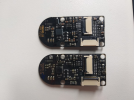
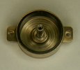
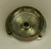
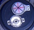
PS: This is the board responsable for "Limp Gimbal", which needs callibration after replacement, I talk about in my post:
1646313894976.png


1646313918858.png

Now
 

Attachments

  • 1646313760815.png
    1646313760815.png
    1.1 MB · Views: 158
I am having same issue after changing the yaw motor and yaw roll motor esc board . Gimbal is facing left side . Anyone can help with yaw motor roll motor esc baord calibratiin tool please. It is not even calibrating with dji firmware tools master (python).
Thanks in advance
 
the only solution which i know is keep changing the yaw roll esc board till it is aligned . dji firmware tolols master (python) not working on phantom gimbals . correct me if i am wrong . some people are having calibration tool for yaw roll esc board . i tried to buy that tool but didn't find anywhere. if someone have the tool to calibrate yaw roll motor esc board then please share . thanks in advance
 
The yaw angle data comes from the motor, there are two analog Hall sensors. It's easier for you to replace the motor.
 
In three disassembled gimbal motors (yaw and roll motors inside are absolutely the same), there were three Hall sensors, that is, half that did not correspond to the datasheet. The correct 5053 sensor puts out 0.5 volts under one pole of the magnet and 2 volts under the other. Some of the sensors output 1 volt and 2.5 volts, respectively. If the sensors are the same - calibration is the easiest - the normal position of the camera is the balance of the signals from both sensors, approximately 1.4 volts. If the sensors are different, soldered crookedly, or the magnetic ring is defective, there will be problems.
 
In three disassembled gimbal motors (yaw and roll motors inside are absolutely the same), there were three Hall sensors, that is, half that did not correspond to the datasheet. The correct 5053 sensor puts out 0.5 volts under one pole of the magnet and 2 volts under the other. Some of the sensors output 1 volt and 2.5 volts, respectively. If the sensors are the same - calibration is the easiest - the normal position of the camera is the balance of the signals from both sensors, approximately 1.4 volts. If the sensors are different, soldered crookedly, or the magnetic ring is defective, there will be problems.
so what did you actually recommend now as solution please
 
I made various experiments: changing the bell with a magnetic ring (usually recommended, no guarantee of success), replacing the Hall pickups (also 50/50), and lastly replacing the magnetic ring with neodymium magnets. I tried to paste 8 magnets 5x5 and 16 (double) 5x3.4 in the last picture, I did not notice the difference. Photos of how to do it below. In the first picture: the magnets are glued with superglue to the 18650 battery case for sanding the corners. The last one is 100% working. Motor torque becomes too high, vibration may occur. Solution: you can set the basic parameters of Gain of Pitch, Roll, Yaw and Vertical to less than the default and additionally I glued lead weights on the camera's IMU board. (IMU sensor smeared with damper grease if you don't know)
 

Attachments

  • DSCN1057.JPG
    DSCN1057.JPG
    436.6 KB · Views: 80
  • DSCN1040.JPG
    DSCN1040.JPG
    848.1 KB · Views: 88
  • DSCN1038.JPG
    DSCN1038.JPG
    970 KB · Views: 78
  • DSCN1033.JPG
    DSCN1033.JPG
    1.2 MB · Views: 79
  • DSCN1031.JPG
    DSCN1031.JPG
    1.1 MB · Views: 82
  • DSCN1030.JPG
    DSCN1030.JPG
    1 MB · Views: 89
  • DSCN1028.JPG
    DSCN1028.JPG
    901.3 KB · Views: 80
  • DSCN1025.JPG
    DSCN1025.JPG
    1.6 MB · Views: 84
there is a part of the old yaw motor assembly that you need to transfer over to the new one, they are calibrated by DJI and without the old part it will never work
 
there is a part of the old yaw motor assembly that you need to transfer over to the new one, they are calibrated by DJI and without the old part it will never work
There is nothing to "calibrate" there. This nonsense has been copied and pasted for years. It's just eight poles of a magnet. And most of them are weak.
 
The board and motor are paired. The board is calibrated to the motor. If you change board u must change motor as well or drill a small hole in the right place on the drum/outer casing to change the magnetic field so as to line up the camera. Changing only one thing will not cure the problem.
 
The board and motor are paired. The board is calibrated to the motor. If you change board u must change motor as well or drill a small hole in the right place on the drum/outer casing to change the magnetic field so as to line up the camera. Changing only one thing will not cure the problem.
FFamiliarize yourself with the topic do not spread fakes. Magnets cannot be programmed. But from it can be pasted crookedly or weakly. I have changed ferrite magnets to neodymium magnets in all gimbal motors. If everything is assembled symmetrically and the north-south poles stand as they should, the suspension works immediately. There are no adjustable, programmable parts. The position of the camera in space is determined by the IMU of the camera based on the MPU6600, the boundary conditions are determined by the Hall sensor DRV5053. The problem with ferrite magnets is that they are often weak for a given Hall sensor and it works to the limit. In the photo, the signal from the Hall sensor, if each of the 8 neodymium magnets is in two parts (it does not bend!). The peaks show the border of two identical poles, they repel each other. But the working area is a decline and rise on a curve. The poles are marked with red and black lines. The black line is "north" out, "south" in.
 

Attachments

  • DSCN1057.JPG
    DSCN1057.JPG
    436.6 KB · Views: 87
  • DSCN1065.JPG
    DSCN1065.JPG
    363.3 KB · Views: 82
I agree the magnet cannot be programmed. But the magnetic field is recorded and "seriallized" by the board. If you are gluing more powerful magnets into your drums and it works then great but what about someone who wants to fix their bird with parts available.?
 
I have worked on these for years. The casing on the yaw motors have magnets that seem to be somewhat random. Using a compass you can figure out where they are. There are about 4 or 5 different casings you have to deal with. If you use the original casing the yaw should point straight ahead. If you don't have the original or it is damaged you can use a compass to figure out which one you need. I have a YouTube video that explains this. You can watch it or not. I am not a super smart guy, I just do what I do.
To view this content we will need your consent to set third party cookies.
For more detailed information, see our cookies page.
 
  • Like
Reactions: bwheelz05
I have worked on these for years. The casing on the yaw motors have magnets that seem to be somewhat random.
I saw your previous post and videos for the yaw motor swap; any tips if that shaft on the yaw motor refuses to back out with a punch?
 
Compass outside the steel screen? This is very inaccurate. Simply measure the field with the available Hall sensors. In addition there are small neodymium magnets, about 2 mm wide, such inside the DVD optics, if they have the poles marked with a marker, they are very good for identifying the motor magnets.
 
I saw your previous post and videos for the yaw motor swap; any tips if that shaft on the yaw motor refuses to back out with a punch?
I have run into that. You could set up a press to do it. I usually just hit it harder. One of 2 things will happen. You will destroy it or it will pop out. Most of the time it pops out. I you destroy the casing, I have hundreds
 
I have run into that. You could set up a press to do it. I usually just hit it harder. One of 2 things will happen. You will destroy it or it will pop out. Most of the time it pops out. I you destroy the casing, I have hundreds
My first attempt to separate my original motor case failed; came back to it a number of weeks later and it worked just fine. Proper sized punch or something... Putting the original motor case on a replacement motor from eBay did fix my issue. Thanks so much Ted.
 

Recent Posts

Members online

Forum statistics

Threads
143,066
Messages
1,467,352
Members
104,933
Latest member
mactechnic