Hello,
I have a P3P with a faulty gimbal.
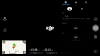
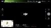
I have control over the pitch of the gimbal but I see no video in app.
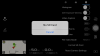
The app says 'No SD'
The app say 'Gimbal Disconnected'.
The Gimbal has no green light on it.
I have tried reformatting but SD in app but it says NO SD.
I have 're-connected' rc and p3p with the app and the small button on side of p3p.
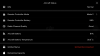
I can't do firmware changes as the p3p cant see the SD card.
Any ideas!?
I note another member called Pnyeguy had the same issue but the thread was inconclusive.
I have a P3P with a faulty gimbal.
I have control over the pitch of the gimbal but I see no video in app.
The app says 'No SD'
The app say 'Gimbal Disconnected'.
The Gimbal has no green light on it.
I have tried reformatting but SD in app but it says NO SD.
I have 're-connected' rc and p3p with the app and the small button on side of p3p.
I can't do firmware changes as the p3p cant see the SD card.
Any ideas!?
I note another member called Pnyeguy had the same issue but the thread was inconclusive.