Yeah, no short from underneath causing the failure... I powered it on outside the drone. It was taped to cardboard to keep it from shifting while I worked on it.Hi Okstuv,
powered on the module on your workbench with external 12VDC from a power supply, or powered on after returning into Phantom and powering on Phantom?
Thanks.


You are using an out of date browser. It may not display this or other websites correctly.
You should upgrade or use an alternative browser.
You should upgrade or use an alternative browser.
lightbridge firmware PROBLEM (and solution) - firmware version not found by dji assistant tool
- Thread starter gaucho
- Start date
- Joined
- Apr 14, 2015
- Messages
- 294
- Reaction score
- 37
- Age
- 76
Today I repaired the LB Air unit received by jhonbull,
I wish to share my experience.
the unit was fried.
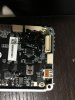
The broken component was the one at upper right in the picture.
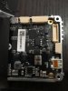
it's a double inductance.
between positive terminal and the load (the LB circuit) there is one inductance.
between negative terminal and the load (the LB circuit) there is one inductance.
this component can be used to filter the input voltage cause the inductance opposes to fast change in current.
this component may get broken if the load becomes too much big (a short circuit[internal or external] or some component drying anomalous current) or if the input voltage changes too much fast (overvoltage due to wrong battery connection or some component generating spikes and overvoltage.
I replaced it with 2 self built inductance obtained with a piece of copper and black silicon.
In order to mechanically reinforce the welding i added silicon all over it and a piece of tap.
I closed everything and now it works again.
I wish to share my experience.
the unit was fried.
The broken component was the one at upper right in the picture.
it's a double inductance.
between positive terminal and the load (the LB circuit) there is one inductance.
between negative terminal and the load (the LB circuit) there is one inductance.
this component can be used to filter the input voltage cause the inductance opposes to fast change in current.
this component may get broken if the load becomes too much big (a short circuit[internal or external] or some component drying anomalous current) or if the input voltage changes too much fast (overvoltage due to wrong battery connection or some component generating spikes and overvoltage.
I replaced it with 2 self built inductance obtained with a piece of copper and black silicon.
In order to mechanically reinforce the welding i added silicon all over it and a piece of tap.
I closed everything and now it works again.
Great work!!!Today I repaired the LB Air unit received by jhonbull,
I wish to share my experience.
the unit was fried.
The broken component was the one at upper right in the picture.
it's a double inductance.
between positive terminal and the load (the LB circuit) there is one inductance.
between negative terminal and the load (the LB circuit) there is one inductance.
this component can be used to filter the input voltage cause the inductance opposes to fast change in current.
this component may get broken if the load becomes too much big (a short circuit[internal or external] or some component drying anomalous current) or if the input voltage changes too much fast (overvoltage due to wrong battery connection or some component generating spikes and overvoltage.
I replaced it with 2 self built inductance obtained with a piece of copper and black silicon.
In order to mechanically reinforce the welding i added silicon all over it and a piece of tap.
I closed everything and now it works again.
- Joined
- Apr 14, 2015
- Messages
- 294
- Reaction score
- 37
- Age
- 76
I opened the Ground unit and i decided to backup the entire flash memory.
I pressed esc during the boot and then i printed the memory with the command md.b 0x0 0xffffffff
the log appears as it follows...
This is the syntax used in the following command: md.b 0x0 0xffffffff
md = name of the command
.b = print the data as bytes separed by spaces
0x0 = starting byte to print
0xffffffff = number of bytes to print
Now with a script on the pc we can convert the ASCII characters to binary file and understand how memory is structured.
while the log was scrolling the unit started to beep.
I supposed it was due to the high temperature (because the chassis was open) and i placed some ice on the LB.
:-D

I found that after some time the device powers off automatically. I suppose it's a safety shutdown procedure.
I had to restart the LB (and then the md command) 4 times. Each time i used as starting point the byte where it stopped.
I stopped at 0x012e57d0 but i have seen that jumping forward at some random memory locations, there is data also forward.it's just a little bit hard because the unit reboots automatically after a while.
p.s.:the md command do not allow to put an address greather than 0xffffffff
I cleaned the Log to show just the memory locations.
Here annexed you find the file: www.tr3ma.com/Dati/logLBGroundUnitMemoryBackupAscii1.zip
@kurkovda do the same and post here your log.
Edit: I found that if i connect the radio joystick on the audio jack connector the LB stops to beep. I suppose that now it will no more automatically power off.
tonight I will left the log to continue from address 0x012e57d0
I pressed esc during the boot and then i printed the memory with the command md.b 0x0 0xffffffff
the log appears as it follows...
Code:
00000000: fe 1f 00 ea 41 fb 2a d5 5c fa f5 6d a0 9c 3c 20    ....A.*.\..m..<
00000010: fc d7 b0 3c 83 7c 68 d1 29 c7 9c 21 52 31 c1 36    ...<.|h.)..!R1.6
00000020: 31 0f 19 ee 01 00 a0 e3 31 0f 09 ee 11 0f 19 ee    1.......1.......
00000030: 38 00 9f e5 1d 00 80 e3 11 0f 09 ee 34 00 9f e5    8...........4...
00000040: 34 10 9f e5 34 20 9f e5 00 00 52 e1 05 00 00 9a    4...4 ....R.....
00000050: 00 20 42 e0 42 21 a0 e1 04 c0 90 e4 01 20 52 e2    . B.B!....... R.
00000060: 04 c0 81 e4 fb ff ff 1a 04 00 9f e5 00 f0 a0 e1    ................
.....
This is the syntax used in the following command: md.b 0x0 0xffffffff
md = name of the command
.b = print the data as bytes separed by spaces
0x0 = starting byte to print
0xffffffff = number of bytes to print
Now with a script on the pc we can convert the ASCII characters to binary file and understand how memory is structured.
while the log was scrolling the unit started to beep.
I supposed it was due to the high temperature (because the chassis was open) and i placed some ice on the LB.
:-D
I found that after some time the device powers off automatically. I suppose it's a safety shutdown procedure.
I had to restart the LB (and then the md command) 4 times. Each time i used as starting point the byte where it stopped.
I stopped at 0x012e57d0 but i have seen that jumping forward at some random memory locations, there is data also forward.it's just a little bit hard because the unit reboots automatically after a while.
p.s.:the md command do not allow to put an address greather than 0xffffffff
I cleaned the Log to show just the memory locations.
Here annexed you find the file: www.tr3ma.com/Dati/logLBGroundUnitMemoryBackupAscii1.zip
@kurkovda do the same and post here your log.
Edit: I found that if i connect the radio joystick on the audio jack connector the LB stops to beep. I suppose that now it will no more automatically power off.
tonight I will left the log to continue from address 0x012e57d0
Last edited:
This thread is becomed a little bit too long to be read.
Thank you for posting this. I really want to give it a try. Can you please post a photo of where you are soldering the wires to the FT232RL 3.3V-5.5V FTDI USB to TTL Serial Adapter? I see 2 TX connections so I'm not sure exactly how to solder the wires to this board. Thank you again!
Last edited:
- Joined
- Apr 14, 2015
- Messages
- 294
- Reaction score
- 37
- Age
- 76
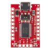
the connector on the left is the one to use. it has a tx an, rx, and a gnd.Thank you for posting this. I really want to give it a try. Can you please post a photo of where you are soldering the wires to the FT232RL 3.3V-5.5V FTDI USB to TTL Serial Adapter? I see 2 TX connections so I'm not sure exactly how to solder the wires to this board. Thank you again!
the tx transmits data and it should go on the pin where the LB expect to receive the data, and equivalent reasoning for the rx. I inverted tx and rx more than one time and nothing was broken.

- Joined
- Apr 14, 2015
- Messages
- 294
- Reaction score
- 37
- Age
- 76
I found that the LB continues to power off even with the radio control sticks connected. I found that you have to move the stiks when it starts to beep and it stops to beep and it stays on.
now i restarted the memory dump from address 0x01a15ad0
now i restarted the memory dump from address 0x01a15ad0
- Joined
- Apr 14, 2015
- Messages
- 294
- Reaction score
- 37
- Age
- 76
while the memory is dumping to text file i wrote the decode tool.
here a screenshot and the sources. the compiled exe is in the subfolder bin/debug

these are sources and compiled file: www.tr3ma.com/Dati/AsciiToBinaryConverter.zip
p.s.: I found that some characters are wrong printed, but these are few cases. I identified it on a error log so you can manually correct them in the bin file.
pps:I found that if you move the stick the LB don't powers it off (may be i still said this..)

p.p.p.s: i found that some memory location are not readable. the md command just hangs.
in thos cases you have to reboot the unit. I'm identifying all the not readable areas and dumping the rest.
here a screenshot and the sources. the compiled exe is in the subfolder bin/debug
these are sources and compiled file: www.tr3ma.com/Dati/AsciiToBinaryConverter.zip
p.s.: I found that some characters are wrong printed, but these are few cases. I identified it on a error log so you can manually correct them in the bin file.
pps:I found that if you move the stick the LB don't powers it off (may be i still said this..)
p.p.p.s: i found that some memory location are not readable. the md command just hangs.
in thos cases you have to reboot the unit. I'm identifying all the not readable areas and dumping the rest.
Last edited:
chaps,
i bought these on ebay.
Wifi Range Extender RE700 and Phantom 2 Vision plus (v3) Wifi module with antennas, so not LB!


it was advertised as "black screen" so it has the NAND issue possibly. if somebody walk me through, I'd try to reflash it. my phantom is with DJI now for repairs so I only have the RE700 and this wifi module with the antennas.
another thought...
what if the RE700 module board can be used as a WiFi board flasher? we can connect to the RE700 via telnet/ssh right?
thinking something like this:

i bought these on ebay.
Wifi Range Extender RE700 and Phantom 2 Vision plus (v3) Wifi module with antennas, so not LB!
it was advertised as "black screen" so it has the NAND issue possibly. if somebody walk me through, I'd try to reflash it. my phantom is with DJI now for repairs so I only have the RE700 and this wifi module with the antennas.
another thought...
what if the RE700 module board can be used as a WiFi board flasher? we can connect to the RE700 via telnet/ssh right?
thinking something like this:
Last edited:
- Joined
- Jul 22, 2016
- Messages
- 36
- Reaction score
- 1
- Age
- 54
Supercool
Why don't you write a thread with the complete description solution, then you can reference this thread if you want.
If you do this I will reference it on the first post.
Hi Gaucho !
used command:
sfh_DM36x.exe -nandflash -v -p "COM8" dm6467_297_ubl.bin u-boot_modifiedByGaucho.img
dm6467_297_ubl.bin (14 372 bytes)
u-boot_modifiedByGaucho.img (294 912 bytes)
I can't flashing my module WM301_DM36x_v1, because flash process is failed. DM36x flasher create file in own folder called sft_DM36x_nand.bin
file containing this message:
initialization failed!
initialization passed!
TI SFT Version: 1.50
Booting Catalog Serial Flasher
DONE Unprotect failed
NAND is write protected!
Number of blocks needed for header and data: 0x NAND block is bad!!!
No good blocks in allowed range!!!
Attempting to start in block number 0x Erase failed
Writing header and image data to Block , Page Write failed!
Write verify failed!
Write failed, skipping block!
Write verify failed, skipping block!
SENDIMG ACK 0000 BADCNT BADADDR BEGIN
UART Receive Error
Starting UART Boot...
BOOTUBL CMD NAND_open() failed! Writing UBL to NAND flash
Writing failed! Writing APP to NAND flash
Erase failed.
Erase completed successfully.
Boot command not supported! H6 DM36x Protecting the entire NAND flash.
Unprotecting blocks through Erasing block Bad Block NO
Erasing is skipped
Erase verification failed! Block: page: . First Failing Byte: Data verification failed! Block:
Do you have opinion? Could you help me?
Thank you for your cooperation!
- Joined
- Apr 14, 2015
- Messages
- 294
- Reaction score
- 37
- Age
- 76
If u read dm36x wiki page about flashing methods, where it describes the use of sfh exe, you will read that the write must be enabled. May be there is some jumper, dip switch or short to make on your board in order to enable the write
Hello guys!
I did buy a almost new dji Lighbridge, only used once for the last past year, and then I bought it. I got the same problem as you have in this thread. My problem is with the groundstation.
I did buy this usb to ttl serial board, can I use that board? see attached picture then solder to gnd, RX and TX onto it, right? and the the other stuff as detailed exlained by Mr gaucho.
I just wanted confirmation that I can use the usb ttl board for this.
regards K
Attachments
OK so first atemot failed. the usb to tll works great BUT!: when I enter this: sfh_DM36x.exe -nandflash -v -p "COM9" ubl1_editedByGaucho.img u-boot_modifiedByGaucho.img
it says: it never says target: BOTTME??? what did I do wrong here?
DM36x initialization passed!
UBL Product Vesion : DJI-ABP-SUPER-UBL-1.0-rc0(2014-08-25)
Dji UBL Version: 1.51(Aug 26 2014 - 16:00:24)
Booting Catalog Boot Loader
BootMode = NAND
Starting NAND Copy...
Valid magicnum, 0xA1ACED66, found in block 0x00000019.
Valid magicnum, 0xA1ACED66, found in block 0x0000001B.
Valid magicnum, 0xA1ACED66, found in block 0x0000001D.
Valid magicnum, 0xA1ACED66, found in block 0x0000001F.
No valid boot image found!
NAND Boot failed.
Aborting...
Sorry for flooding this thread:
Problem solved, THANX GUYS! my unit is now working again!
best Regards //K
Problem solved, THANX GUYS! my unit is now working again!
best Regards //K
hello again!
Can anyone tell me how to get android app working? after this fix I cannot get any connection to the app?
says "connection broken"?
otherwise it all works fine with my HDMI monitor etc, but I cannot use the app and change settings. and when I try it says " settings send failed"
Can anyone tell me how to get android app working? after this fix I cannot get any connection to the app?
says "connection broken"?
otherwise it all works fine with my HDMI monitor etc, but I cannot use the app and change settings. and when I try it says " settings send failed"
- Joined
- Apr 14, 2015
- Messages
- 294
- Reaction score
- 37
- Age
- 76
the memory structure analysis is a long work, i still didn't finished. Since the user that needs this information is no more writing on this forum i will stop to do it.
this is the point where i arrived:
Note: All values are in hex format
here annexed the file 1 and 2_1
this is the point where i arrived:
Note: All values are in hex format
Code:
Description                   StartAddress       StopAddress   Size
LBFile1.bin                   0                           1f                       20
ubl1.img                       20                       381f                   3800
LBFile2_1.bin               3820                   1001f               C800
ubl1.img                       10020                   1381f               3800
LBFile2_1.bin               13820                   2001f               C800
ubl1.img                       20020                   2381f               3800
LBFile2_1.bin               23820                   3001f               C800
ubl1.img                       30020                   3381f               3800
LBFile2_1.bin               33820                   4001f               C800
ubl1.img                       40020                   4381f               3800
...........................
here annexed the file 1 and 2_1
Attachments
- Joined
- Apr 14, 2015
- Messages
- 294
- Reaction score
- 37
- Age
- 76
hello again!
Can anyone tell me how to get android app working? after this fix I cannot get any connection to the app?
says "connection broken"?
otherwise it all works fine with my HDMI monitor etc, but I cannot use the app and change settings. and when I try it says " settings send failed"
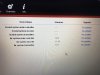
can you see the 3 firmware version on the upgrader tool?
did you upgraded all 3 firmware components after following my procedure?
can you connect the internal serial port and show the full boot log? can you post it here?
the memory structure analysis is a long work, i still didn't finished. Since the user that needs this information is no more writing on this forum i will stop to do it.
this is the point where i arrived:
Note: All values are in hex format
Code:Description StartAddress StopAddress Size LBFile1.bin 0 1f 20 ubl1.img 20 381f 3800 LBFile2_1.bin 3820 1001f C800 ubl1.img 10020 1381f 3800 LBFile2_1.bin 13820 2001f C800 ubl1.img 20020 2381f 3800 LBFile2_1.bin 23820 3001f C800 ubl1.img 30020 3381f 3800 LBFile2_1.bin 33820 4001f C800 ubl1.img 40020 4381f 3800 ...........................
here annexed the file 1 and 2_1
Ahhh ok!
to bad that user is not active anymore =(. So you have the same problem as me regarding the usb port and android device? HAve they completly deleted the app for ios devices? or can I get it somewhere?
those hex values, did you get the from the terminal u wrote?
can you see the 3 firmware version on the upgrader tool?
did you upgraded all 3 firmware components after following my procedure?
can you connect the internal serial port and show the full boot log? can you post it here?
I use the dji lightbridge assistant 1.3(latest) and yes I see all 3 firmware and I installed them , one by one. no problem there at all.
hmm ok then I have to resolder the usb to ttl device and get the boot log if u still want it?
btw how do I get the bootlog?
- Joined
- Apr 14, 2015
- Messages
- 294
- Reaction score
- 37
- Age
- 76
Ahhh ok!
to bad that user is not active anymore =(. So you have the same problem as me regarding the usb port and android device? HAve they completly deleted the app for ios devices? or can I get it somewhere?
those hex values, did you get the from the terminal u wrote?
i found ios app one time as offline download then i lost it.
no, i don't have your problem.
I converted the hex print (read previous posts) to binary file. So we could understand what and where to write data to memory, by means of uboot and not only via windows tool sfh. this because sfh exe is less flexible and if also have a bug that does not allow you to write memory location where you want.
anyway this should be usefull just in particular cases. most of the cases it will be fine the procedure reported on the first post.


