I think the research here is excellent, but I want to ask if those with stress cracks found, balanced their props right away before flying for the first time? I have 3 sets of stock dji props and 1 set of CF re-inforced props and all of them were way off balance.. I balanced them before I flew my initial flight and have logged >100 hours with no sign of stress cracks. Just saying that it may help others who are worried


You are using an out of date browser. It may not display this or other websites correctly.
You should upgrade or use an alternative browser.
You should upgrade or use an alternative browser.
- Joined
- Aug 4, 2015
- Messages
- 59
- Reaction score
- 24
- Age
- 40
I balanced mine right out of the box. Granted my issue was cracks around the motor mounts and not the usual 2 shell screws but none the less it cracked..I think the research here is excellent, but I want to ask if those with stress cracks found, balanced their props right away before flying for the first time? I have 3 sets of stock dji props and 1 set of CF re-inforced props and all of them were way off balance.. I balanced them before I flew my initial flight and have logged >100 hours with no sign of stress cracks. Just saying that it may help others who are worried
- Joined
- Jun 25, 2015
- Messages
- 621
- Reaction score
- 194
- Age
- 62
I know when I began reading about these cracks I loosened all the screws. Almost all were quite tightly torqued popped loudly when they came loose. I re-torqued them to only a few inch-pounds, if that. They are snug and all have bright orange torque stripe on them. Been flying for over a month like that and just checked today no cracks and all the torque indications have not moved.I wonder if heat is such a problem? Plastics tend to crack more with cold than heat - they become more "plastic" when they are warm!
I suspect over tightening and maybe prop vibrations are the main culprits.
Going to bust out the FLIR camera tomorrow and get some quantitative temperature measurements.
Last edited:
Got it.. I think maybe a combination of releasing the screw torque and prop balancing may be a good compromise to address this until the design is beefed up a bitI balanced mine right out of the box. Granted my issue was cracks around the motor mounts and not the usual 2 shell screws but none the less it cracked..
- Joined
- Aug 21, 2015
- Messages
- 5
- Reaction score
- 5
found another thing, it seems that the arm motor base support (4 circles) doesn't have same length (1mm). But, the motor base has a flat one. (yes I'am aware that tilting motor for quad is nothing new).
But this way, I wonder about the vibration effect of the tilted screw on the plastic.
But this way, I wonder about the vibration effect of the tilted screw on the plastic.
- Joined
- Jun 25, 2015
- Messages
- 621
- Reaction score
- 194
- Age
- 62
Take a second look at that FLIR photo. The screws are much cooler than the motor area. Either they dissipated heat quickly, or they did not conduct much heat at all.
I should have thought about this comment when I first read it but it wasn't until I was preparing to shoot some pictures of my P3 heating up this morning it dawned on me. The screws are made from steel and by nature have a emissivity of something in the neighborhood of 0.7 to 0.03 so the temperature you is NOT the temperature you get. There may be some amount of cavity effect with the design but the surfaces will still skewing the temperatures considerably. I will be able to work around that during my shoot.
- Joined
- Jun 25, 2015
- Messages
- 621
- Reaction score
- 194
- Age
- 62
So earlier today I prepped the P3 for an infrared photo shoot by putting some Super 33+ on three of the 4 screws holding the motors on the arms, plus a little around here and there for comparison to the P3's plastic. Super 33 has an emissivity of 0.97 or so.

So then I took her out for a flight, POI at 120 feet AGL 75 feet radius at 20 miles per hour, 15 minutes or so, it was hovering 5 feet above the ground when the landing in 10 seconds warning brought her to the ground. Immediately flipped her over and shot this picture of the motor screws. I have always liked the greyscale images in white=hot for most all analysis. As you can see in the table in the right three screws read 115 Fahrenheit, the screw without Super 33 read some weird average of the sky above (typically reads <-22F) and everything else reflected. With an average emissivity of who knows what, they must be reined in to some definable value that is why I put the electrical tape on them.

So for anyone wanting to analyze thermal images I am attaching the original FLIR images, hopefully they will retain the full 12 bits per pixel. Search FLIR Tools download and get the 200 megabyte program to do analysis it is very interesting I think. I added colors for those that prefer rainbows and such. Easy operation in the tools program. Sometimes brings out contrasts in temperature you would not see otherwise.
Before flight

Super 33 on upper half of motor, after flight

Motor after flight, not taped (shows extremely low emissivity of motor body)

Screws after flight-No super 33

After flight 3 screws have Super 33 on them

Upsidedown P3 after 15-20 minute flight

right side up after flight with a butterfly and it's reflection on top skin

ciao
FLIR Tools for mac and pc link
FLIR Tools Software for Mac and PC | FLIR Systems
So then I took her out for a flight, POI at 120 feet AGL 75 feet radius at 20 miles per hour, 15 minutes or so, it was hovering 5 feet above the ground when the landing in 10 seconds warning brought her to the ground. Immediately flipped her over and shot this picture of the motor screws. I have always liked the greyscale images in white=hot for most all analysis. As you can see in the table in the right three screws read 115 Fahrenheit, the screw without Super 33 read some weird average of the sky above (typically reads <-22F) and everything else reflected. With an average emissivity of who knows what, they must be reined in to some definable value that is why I put the electrical tape on them.
So for anyone wanting to analyze thermal images I am attaching the original FLIR images, hopefully they will retain the full 12 bits per pixel. Search FLIR Tools download and get the 200 megabyte program to do analysis it is very interesting I think. I added colors for those that prefer rainbows and such. Easy operation in the tools program. Sometimes brings out contrasts in temperature you would not see otherwise.
Before flight
Super 33 on upper half of motor, after flight
Motor after flight, not taped (shows extremely low emissivity of motor body)
Screws after flight-No super 33
After flight 3 screws have Super 33 on them
Upsidedown P3 after 15-20 minute flight
right side up after flight with a butterfly and it's reflection on top skin
ciao
FLIR Tools for mac and pc link
FLIR Tools Software for Mac and PC | FLIR Systems
Attachments
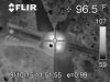

Take a second look at that FLIR photo. The screws are much cooler than the motor area. Either they dissipated heat quickly, or they did not conduct much heat at all.
The plastic around the screws is helping to dissipate the heat, that's why they are cooler.
The work-around would be to use some aluminum support on the outside under the motor mounts and use longer screw.
If you have some spare brushless motor mounts like I do them these will work perfectly. I think I am going to do this on mine .
Attachments
Last edited:
- Joined
- May 27, 2014
- Messages
- 105
- Reaction score
- 9
What does it take for a class action lawsuit against DJI for this very expensive design flaw? I have been pretty upset that my P3P cracked within 60 days and got so bad (even after epoxy) I had to ground my bird and fix it myself because I refuse to send it back and wait 60+ days. Now another $60 into a repair that surely should have been avoided. And we all know I'm one of thousands.
- Joined
- Oct 4, 2014
- Messages
- 40
- Reaction score
- 3
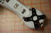
I was thinking (being in manufacturing myself) there could be a few reasons for the cracking problem on the P3.
- Flight fatigue and stress over time
- Off Balance motor due to rotor damage
But look at this, a FLIR image of a P3 after about 1 minute of hovering
View attachment 30029
Heat buildup from the motor is NOT good for the plastic. Combine that with vibration and over a period of time you get brittle arms. I saw a number of 3d printed re-inforcing plates - this could in fact increase the heat issue What we actually need is machined aluminium plates, those will acted as a heatsink as well..
Any thoughts?
Take a second look at that FLIR photo. The screws are much cooler than the motor area. Either they dissipated heat quickly, or they did not conduct much heat at all.
As you may know, interpreting an IR image can be very difficult, and often incorrect, especially since viewers were not present during the flight and imaging. There are several factors to consider which will artificially "heat" up the "apparently" hot screws. 1-heat from the camera operator, 2-background radiation source, possibly from above-, i.e. sun, overhang, 3-camera operator error and uncalibrated camera, 4-emissivity of plastic vs metal screws, 5-convective cooling.
- Joined
- Oct 19, 2013
- Messages
- 114
- Reaction score
- 38
Depends on how you fly it. However, if you attach the removable prop guards on each arm, it seems to give the copter more strength. After seeing this, I’m going to leave them on there even if i don’t use the prop guards.I was thinking (being in manufacturing myself) there could be a few reasons for the cracking problem on the P3.
- Flight fatigue and stress over time
- Off Balance motor due to rotor damage
But look at this, a FLIR image of a P3 after about 1 minute of hovering
View attachment 30029
Heat buildup from the motor is NOT good for the plastic. Combine that with vibration and over a period of time you get brittle arms. I saw a number of 3d printed re-inforcing plates - this could in fact increase the heat issue What we actually need is machined aluminium plates, those will acted as a heatsink as well..
Any thoughts?
- Joined
- Oct 19, 2013
- Messages
- 114
- Reaction score
- 38
This statement did not make any sense at all and how you zipped the ends did really nothing to fix the issue he was describing. DJI needs to know this information to make a better copter.Hey, Just zip them up and go out and enjoy your quad. Life's too short to worry about things you have very little control over. They will crack if they want to, All you can do is try to hold things together if they do
View attachment 30045
")
I think you may be onto something. Heat is not good for plastic. I would also observe that a plastic motor mount is a poor choice for a design. Plastic as a case is a poor aircraft body choice. Does anyone know if someone can get 3D plans for the shell so someone can print a shell out of fiberglass? I think fiberglass would be much stronger and lighter, and also support signal poke-through the shell for GPS and other radio links.I was thinking (being in manufacturing myself) there could be a few reasons for the cracking problem on the P3.
- Flight fatigue and stress over time
- Off Balance motor due to rotor damage
But look at this, a FLIR image of a P3 after about 1 minute of hovering
View attachment 30029
Heat buildup from the motor is NOT good for the plastic. Combine that with vibration and over a period of time you get brittle arms. I saw a number of 3d printed re-inforcing plates - this could in fact increase the heat issue What we actually need is machined aluminium plates, those will acted as a heatsink as well..
Any thoughts?
This is my worst nightmare: Crashes.
For now i did buy to a user on RCgroups a balancer for the propellers.
Apart that.....im very carefull when i atach and remove the propellers, and carry the P3 by hands only in the middle of it.
The rest is......lucky!
For now i did buy to a user on RCgroups a balancer for the propellers.
Apart that.....im very carefull when i atach and remove the propellers, and carry the P3 by hands only in the middle of it.
The rest is......lucky!
Sorry but fiberglass (FRP) would be far heavier, probably two to three times as heavy. Also, even if you could meet the weight, it's a much pricier means of making a shell. My estimate would be on the order of 400-500% higher.I think you may be onto something. Heat is not good for plastic. I would also observe that a plastic motor mount is a poor choice for a design. Plastic as a case is a poor aircraft body choice. Does anyone know if someone can get 3D plans for the shell so someone can print a shell out of fiberglass? I think fiberglass would be much stronger and lighter, and also support signal poke-through the shell for GPS and other radio links.
One other thing, you don't "Print a shell out of fiberglass" Fiberglass is resin impregnated fiberglass cloth, or chopped roving sprayed up simultaneous with the resin.
Sorry but fiberglass (FRP) would be far heavier, probably two to three times as heavy. Also, even if you could meet the weight, it's a much pricier means of making a shell. My estimate would be on the order of 400-500% higher.
One other thing, you don't "Print a shell out of fiberglass" Fiberglass is resin impregnated fiberglass cloth, or chopped roving sprayed up simultaneous with the resin.
Obviously plastic is cheap, and why they are using it. I would think fiber reinforced resin could be 3D printed. Or what about carbon fiber? It's expensive, but if someone could make a case out of it, and somehow make the GPS antenna part of it as plastic, this would surely be stronger and lighter. Or even if they just made a main body "X" and the engine mounts out of carbon fiber and stuck with the plastic just to cover the rest, and not really have plastic be a stress bearing part of the frame that would be better. I wish someone would have a real fix for this. These things cannot be falling out of the sky from cracking, I would think DJI would want to fix this also. Depending on how some fly, this could be dangerous.
- Joined
- Oct 4, 2014
- Messages
- 40
- Reaction score
- 3
Further test and photos.
After 30 minutes of flight (2 batteries) in an ambient sunny temperature of around 25 degrees C the max temperature that the motors reached was 38 on the bottom of the plastic.
With my limited knowledge of plastic's I will concur with what a few said in this thread - It is not of such great concern.
I would - if I have a choice between plastic and Aluminium supports, go for the latter, but it's not the end of the world.
Any plastic's experts for an opinion?
View attachment 30135
View attachment 30137 View attachment 30138
If you wouldn't mind posting the raw IR images, I might be able to dig deeper into the temps.
You're a freaking genius... I don't have the FLIR for my iPhone but what you did was excellent.I was thinking (being in manufacturing myself) there could be a few reasons for the cracking problem on the P3.
- Flight fatigue and stress over time
- Off Balance motor due to rotor damage
But look at this, a FLIR image of a P3 after about 1 minute of hovering
View attachment 30029
Heat buildup from the motor is NOT good for the plastic. Combine that with vibration and over a period of time you get brittle arms. I saw a number of 3d printed re-inforcing plates - this could in fact increase the heat issue What we actually need is machined aluminium plates, those will acted as a heatsink as well..
Any thoughts?
You're right about the heat sink idea... perhaps not only aluminum reinforcement plates for the motor mounts but make them with small fins so as to increase surface that would aid in heat dispersement and increased cooling capability? Wow, sorry, I guess I should look through the entire thread before putting in my comments / ideas.
Similar threads
- Replies
- 1
- Views
- 2K
- Replies
- 4
- Views
- 2K
- Replies
- 1
- Views
- 1K


