rv6tc said:
Plut0nius,
Did you figure this out?
I modded my transmitter today and I'm good through about half travel of the pot, but beyond that, I get a split similar to what you are seeing. I'd like to know if you figured it out.
Thanks.
Greetings rv6tc and fellow late-night modders,
It has been 10 educational days since I last posted.
Thank you SpikeFinch for producing your instructional video, this has been motivating for those with little experience but ample will.
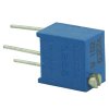
Seeing the previous video of the 10K potentiometer yaw speed, I figured like many might, "More is Better". Thus, I installed a 20K Mouser potentiometer controlled with a simple toggle. The switched circuit worked.
However, I quickly realized the maximum left/right rudder values via the RC application were highly asymmetrical and the neutral position was not zero, even after calibration with the mod switch off.
These asymmetrical rudder values corresponded with actual asymmetrical yaw speeds when flight tested.
Not good. Untenable. "More is Less"
Ultimately, I reached out to cougar.
Over the following days, he guided me (like Virgil in the Inferno) through the basic principles and techniques and encouraged me to logically and systematically test each component.
Multimeter time.
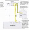
I unsoldered the mod and began to test the OEM yaw gimbal to determine if the outputs (yellow and black wires) are equal (in ohms). For full reference and curiosity I also tested the right stick roll gimbal outputs.
To test for innate balance:
1. Unplug the connector of the yaw gimbal to the circuit board.
2. Stick very thin solid wires into either the black or yellow and gray female portion on the now loose connector.
3. Keep the yaw stick in neutral position.
3. Use your multimeter and connect to a coloured wire (using the added thin solid wire as the contact point) and the gray.
4. Take note of this value.
5. Repeat with the other coloured wire and gray.
6. These ohm values should be very near equal and roughly in the 4.5K to 4.8K range.
7. If they are not equal, you will need to add a resistor with an ohm value of this difference to the wire that has the lesser of the resistances.
My internal yaw gimbal was spot on equal. My roll gimbal was as well. Thus I knew logically the asymmetrical rudder values were coming from the 20K pot, barring any faulty solder connection or broken wire...
This was my fundamental lesson of this mod:
The Mouser pots are really not worth a pot for the hoped for intent of this mod.
That is, pay head to the term "tolerance" when purchasing these variable resistors. a +-10% tolerance on 20000 ohms is up to 2000 ohms. This is a big deal when one is intending for precision. As you dial up the resistance with this pot, you begin to see the loss of precision and greater asymmetry of the rudder values/yaw speeds. Try finding a 1%-5% tolerance pot. big money, my friends. Or you can go the digital pot route... knowledge is power.
Test your pot's ohms with a multimeter and see what a difference there is between the black and yellow leads.
So, my second important lesson of this mod was:
I do not need a variable resistor. A fixed one satisfies the true intent of this mod.
What is the ultimate purpose of this mod?
Its all about the silky smooth panning for high quality video capture.
Thus, I began the (rather fun) trial and error process of testing the ohms through of the system by adding resistors, one at a time on each line, black and yellow, just before the 20K pot on the circuit. Test each resistor before placing them inline. Find a pair of resistors that match.
I was looking for a yaw speed of about 10% of the maximum rudder values of -1000/1000, thus mathematically about -100/100.
I ended my testing with this configuration:
25147 ohms on the Black line (two 10K, one 5.1K and one 47)
25100 ohms on the Yellow line (two 10K and one 5.1K)
Now I can flip the toggle and immediately have balanced ultra-slow smooth left and right yaw speeds. My rudder values in the RC app are near perfectly balanced at maximum left/right -113/115, respectively and neutral stick at 0.
"Less is more"
The 20K pot is still in the circuit. This is the joker element now.
I have it turned to off, to least resistance. But I can use it if I want to eke out a little bit more balanced resistance. Only to about -100/100, after this, it begins to develop asymmetry in speed/RC rudder values, and neutral becomes non-zero.
I re-soldered my re-mod as per the original RemE-Lars schematics to avoid confusion of multi wire contact points on the DPST switch pins (for more accurate circuit testing its best to have separate junctions).
However, both SpikeFinch's and RemE-Lars methods produced the identical asymmetrical results before I placed fixed resistors.
This has been an excellent experience. My local radio shack dudes would laugh when I walked in. They kept saying "you couldn't resist"
now maybe onto the camera tilt pot mod...
or maybe the T14 SG...
Thanks to cougar for his patience.