Battery Error After Replacing Cells

Joined
May 7, 2025
Messages
14
Reaction score
0
Age
27
Hello everyone,

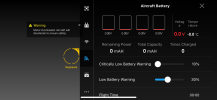
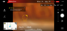
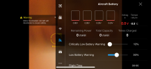
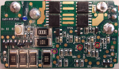
I'm having an issue with one of my batteries for my Phantom 3 Standard. For some context, I have 3 batteries, however I think I must've let them sit for too long as two of them experienced power failure after the individual cells dropped too low in voltage. To make a long story short, I opened up the batteries, removed the old cells, spot welded in new ones, and used the Battery Killer software to clear the power failure flag. After closing them back up, one of the batteries gives me a Battery Error message in the app accompanied by a motor overload message. The other battery seems to work just fine. I honestly can't figure out what the issue might be as from what I've seem, this issue is normally caused by something being wrong with the communication pins in the battery compartment, but since two of my batteries work just fine, I would think that's not the issue. Does anyone have any idea what the issue may be? I'm attaching some screenshots from the app to show exactly what I'm seeing.
 

Attachments

  • IMG_5133.PNG
    IMG_5133.PNG
    422.3 KB · Views: 25
  • IMG_5134.PNG
    IMG_5134.PNG
    1.4 MB · Views: 23
  • IMG_5135.PNG
    IMG_5135.PNG
    1 MB · Views: 23
The uC in your battery doesn't seem to be responding.

If contacts are fine, then the uC either needs reset, or you've fried it while spot welding.
You may also check whether the uC is powered - it should always be working, even if the battery is off.
 
  • Like
Reactions: RodPad
  • Like
Reactions: RodPad
Ah so the u was for "micro". That makes sense now. I actually just was on that Github page so see if I could figure out what it was.

Yes the battery button seems to be working fine. It lets me turn the battery on, shows charge, and even lets me see the battery health.
 
Ok so I went ahead and did what I believe was a reset of the uC following the discussion in this post. What I did was take some wire and just touched one end to the GND pad and the other end to the RST pad. After a few seconds the green lights came on which I took to mean that the reset was successful. I turned the battery off, put it back together, and put it in my drone to test it, but unfortunately that did not seem to solve the problem. I did however notice something that I failed to mention originally. I'm not sure if it's a sign of something, but when the battery is in the drone and I turn it off, the green lights go off but the red light of the power button slowly flashes for around 5 seconds or so before turning off.
 

Attachments

  • P3-Battery-Intellig-boardv1a-top.png
    P3-Battery-Intellig-boardv1a-top.png
    5.2 MB · Views: 10
when the battery is in the drone and I turn it off, the green lights go off but the red light of the power button slowly flashes for around 5 seconds or so before turning off.
The battery sends an announcement before turning off. Then it is waiting for a response "ready to be turned off" before disconnecting MOSFETs.

What you described is the situation when the battery sends the announcement, but no response comes.
 
That makes sense from what we've seen thus far. It looks like the BMS is fine, but for some reason, the uC isn't communicating properly with the drone.

The possibility was brought up earlier that I could've fried something related to the uC when I spot welded the cells. I find that highly unlikely because based on the schematic I've seen, I never had a direct connection to the uC from the board where the batteries are welded. As a matter of fact, it looks like there is no direct connection from the uC to that board, only from the BMS to that board.
 
Yeah, check the UART traces. They're clearly the culprit.
There is slight possibility of UART being selectively fried within the uC, but it's not the most likely solution.
 
It looks like we're on the same page and thinking the same thing. I've looked at the board and couldn't see any shorts or anything else of concern like broken wires. I've gone over the Github page and if I'm not mistaken, the UART traces responsible for data are SCL and SDA?

I'm attaching a picture of the top on my board as that is where I soldered. One other thing I'm remembering is that while I was desoldering the wires I had coming from my CP2112, specifically the GND wire, the green lights came on. I'm not sure if that's relevant or not, but I thought it would be worth mentioning.
 

Attachments

  • IMG_5404.jpg
    IMG_5404.jpg
    626.9 KB · Views: 11
I'm unsure of the best way to check the UART traces. I very briefly this morning tried testing continuity from the SDA and SCL contacts of the connector that goes to the drone to the pins on the uC, and I was able to get continuity for one of them (unfortunately, I can't remember which one). When I did get continuity, the green lights came on like when I reset the uC. It's possible I may have shorted two pins together with my probe and that's why it occurred. I was unable to get continuity from the other contact. I can try again later when I get home in a more careful manner, but any suggestions on what exactly I should be checking and how? I'm attaching a picture of the bottom of the board (courtesy of the Github page) for reference.
 

Attachments

  • P3-Battery-Intellig-boardv1a-btm.png
    P3-Battery-Intellig-boardv1a-btm.png
    3.1 MB · Views: 12
t's possible I may have shorted two pins together with my probe and that's why it occurred.
If you don't have precise probes for your multimeter, you can buy those cheaply from china.

any suggestions on what exactly I should be checking and how?
First check between the output connector and the proper uC pads. Then when you know the faulty one, try narrowing the distance, to figure out where exactly is the break point. Then you should fix that by soldering a thin wire (I also bought such wire from china).

Not much to explain here, thing is very simple. If you have probes with thin needles, and you're able to focus enough to not shake them all over the place, then you can measure it. In case of issues with measuring between other sides of the board, you can solder a wire early on one side and use the probe only for the second.

Figuring out where the traces go should be easy as well - on the image you've pasted there's that connector with SCL/SDA - you can easily spot how the traces are below the connector and then go near the edge of the board, before jumping to the other side by the vias.

For which uC pads should it connect to - you probably have to check the uC datasheet and its pinout there.

(btw, SDA/SCL is not a proper name for UART lines, this is I2C convention; but I guess Chinese engineers don't care for proper markings).
 
If you don't have precise probes for your multimeter
Just want to clarify that my probes are fine. I was checking the continuity as I was in the process of leaving that morning, so it wasn't very precise.

So I've taken some time to check continuity between various points, and I'd like to share what I've found. First off is that I'm not getting continuity directly to any leg of the uC. That's not too concerning to me though because it's entirely possible that there are other components the traces go through that increase resistance.

P3-Battery-Intellig-boardv1a-btm-mq_markup.jpg


So assuming that those two vias at the bottom belong to SDA and SCL of the connector, I've followed them through to the other side of the board. I've marked SCL as red and SDA as blue.

P3-Battery-Intellig-boardv1a-top_markup.png

SCL has continuity to TP13 and the leg of that one component. It's hard to see exactly where the via is, but I believe it is in the "P" of TP15. The other via which I believe belongs to SDA has continuity to TP15 and the other leg of the same component. What's interesting to note is that I haven't seen continuity from SDA on the connector to anywhere on the board, with the sole exception of where the SDA wire is soldered. I'm not getting continuity to TP15 or the leg. This to me is indicating an issue with SDA from the connector to the board.
 
Ok so I believe I can say with certainty that SDA is the problem here. I found out that TP15 and the leg of the component are also shorted to GND. I thought that was odd since following the via to that location, I thought it for sure belonged to SDA. I hadn't really noticed this before, but there is some damage on my board. I only realized this once I compared my board to pictures online.
IMG_5483.jpg

I think what must have happened is that when I opened the casing with a utility knife, I must've gone in just a tad too much and hit the board. I flattened out that area using a small plastic tool, and here's what I have now:
IMG_5484.jpg

There's just the tiniest amount of the trace exposed, so with careful probing, I can get continuity to SDA from that area. The question now becomes how do I fix this. SDA is not shorted to GND, but the rest of its path is, so I think if was to repair the trace, it would short SDA to GND. That would also happen if I simply connected a wire from TP15 to SDA.
 
Note that these are logically not SDA and SCL (not I2C), but RX and TX (UART).
It is possible that there is a PNP transistor which shorts TX to ground when turned off, to avoid floating signals being interpreted as something by the other side.
 
It is possible that there is a PNP transistor which shorts TX to ground when turned off, to avoid floating signals being interpreted as something by the other side.
I had to read that a couple of times before I understood what you were saying. So if there's a PNP transistor, it could be shorting TX to GND to prevent a floating signal when off, but then it opens or closes to break the short to GND when on. That makes sense so I went and checked continuity when the battery was turned on and it is still shorted to GND. Maybe it's different when it's actually plugged into the drone? You did get me thinking that it is a bit odd that one side of the trace is shorted to GND while the other isn't.
 
I went and checked continuity when the battery was turned on and it is still shorted to GND.

Then there really could be an unwanted short. While this may vary, most UART implementation are high when idle. Meaning you should get either 3,3V or 5V to ground on the lines, high impedance on RX one and low impedance on TX.

Then again, this may vary..
 

Members online

Forum statistics

Threads
143,552
Messages
1,471,385
Members
105,536
Latest member
Aeria