Battery Error After Replacing Cells

Joined
May 7, 2025
Messages
10
Reaction score
0
Age
27
Hello everyone,

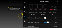
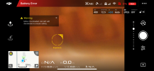
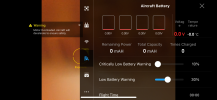
I'm having an issue with one of my batteries for my Phantom 3 Standard. For some context, I have 3 batteries, however I think I must've let them sit for too long as two of them experienced power failure after the individual cells dropped too low in voltage. To make a long story short, I opened up the batteries, removed the old cells, spot welded in new ones, and used the Battery Killer software to clear the power failure flag. After closing them back up, one of the batteries gives me a Battery Error message in the app accompanied by a motor overload message. The other battery seems to work just fine. I honestly can't figure out what the issue might be as from what I've seem, this issue is normally caused by something being wrong with the communication pins in the battery compartment, but since two of my batteries work just fine, I would think that's not the issue. Does anyone have any idea what the issue may be? I'm attaching some screenshots from the app to show exactly what I'm seeing.
 

Attachments

  • IMG_5133.PNG
    IMG_5133.PNG
    422.3 KB · Views: 23
  • IMG_5134.PNG
    IMG_5134.PNG
    1.4 MB · Views: 22
  • IMG_5135.PNG
    IMG_5135.PNG
    1 MB · Views: 21
The uC in your battery doesn't seem to be responding.

If contacts are fine, then the uC either needs reset, or you've fried it while spot welding.
You may also check whether the uC is powered - it should always be working, even if the battery is off.
 
  • Like
Reactions: RodPad
  • Like
Reactions: RodPad
Ah so the u was for "micro". That makes sense now. I actually just was on that Github page so see if I could figure out what it was.

Yes the battery button seems to be working fine. It lets me turn the battery on, shows charge, and even lets me see the battery health.
 
Ok so I went ahead and did what I believe was a reset of the uC following the discussion in this post. What I did was take some wire and just touched one end to the GND pad and the other end to the RST pad. After a few seconds the green lights came on which I took to mean that the reset was successful. I turned the battery off, put it back together, and put it in my drone to test it, but unfortunately that did not seem to solve the problem. I did however notice something that I failed to mention originally. I'm not sure if it's a sign of something, but when the battery is in the drone and I turn it off, the green lights go off but the red light of the power button slowly flashes for around 5 seconds or so before turning off.
 

Attachments

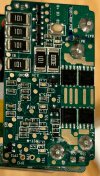
  • P3-Battery-Intellig-boardv1a-top.png
    P3-Battery-Intellig-boardv1a-top.png
    5.2 MB · Views: 4
when the battery is in the drone and I turn it off, the green lights go off but the red light of the power button slowly flashes for around 5 seconds or so before turning off.
The battery sends an announcement before turning off. Then it is waiting for a response "ready to be turned off" before disconnecting MOSFETs.

What you described is the situation when the battery sends the announcement, but no response comes.
 
That makes sense from what we've seen thus far. It looks like the BMS is fine, but for some reason, the uC isn't communicating properly with the drone.

The possibility was brought up earlier that I could've fried something related to the uC when I spot welded the cells. I find that highly unlikely because based on the schematic I've seen, I never had a direct connection to the uC from the board where the batteries are welded. As a matter of fact, it looks like there is no direct connection from the uC to that board, only from the BMS to that board.
 
Yeah, check the UART traces. They're clearly the culprit.
There is slight possibility of UART being selectively fried within the uC, but it's not the most likely solution.
 
It looks like we're on the same page and thinking the same thing. I've looked at the board and couldn't see any shorts or anything else of concern like broken wires. I've gone over the Github page and if I'm not mistaken, the UART traces responsible for data are SCL and SDA?

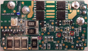
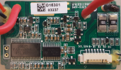
I'm attaching a picture of the top on my board as that is where I soldered. One other thing I'm remembering is that while I was desoldering the wires I had coming from my CP2112, specifically the GND wire, the green lights came on. I'm not sure if that's relevant or not, but I thought it would be worth mentioning.
 

Attachments

  • IMG_5404.jpg
    IMG_5404.jpg
    626.9 KB · Views: 5

Recent Posts

Members online

Forum statistics

Threads
143,543
Messages
1,471,311
Members
105,521
Latest member
tanglefoot