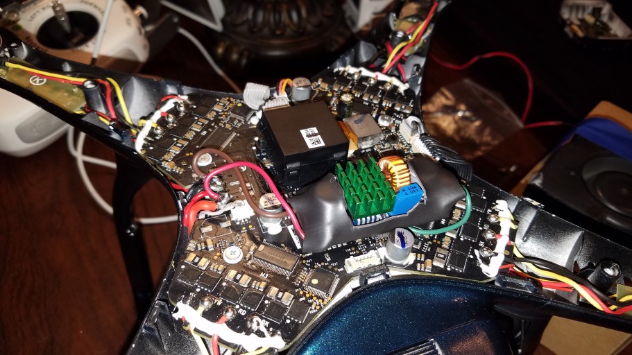
I am having a problem of my main board not delivering 5v to the VPS/OFDM. I need to know if anyone has identified some of the components on the main ESC board? I know that the chips on the outer edge are the ESC's I am mainly looking for info on where the 5v regulator is. This is the newer board for the 800kv motors if that matters, which it probably doesn't. Any help, diagrams appreciated. I found this tidbit so far on another site. View media item 2031
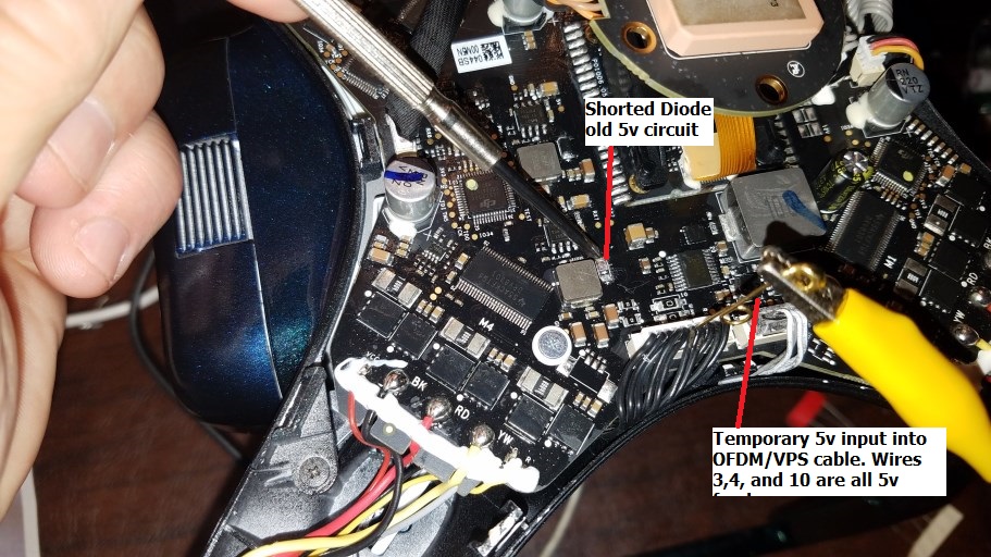
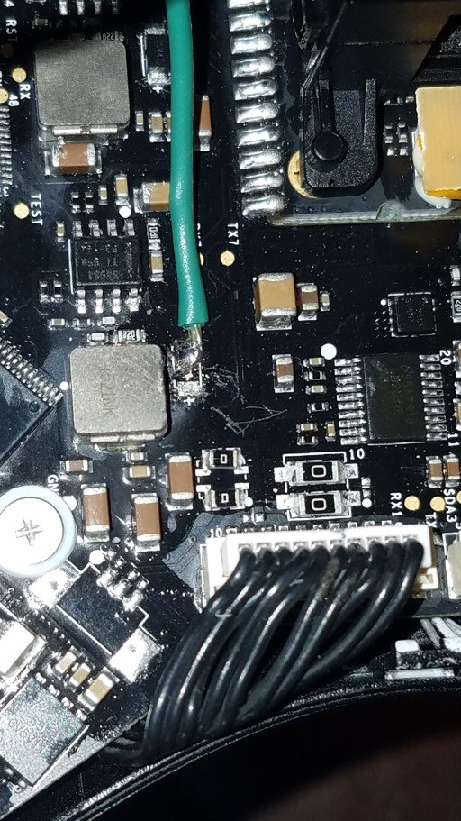
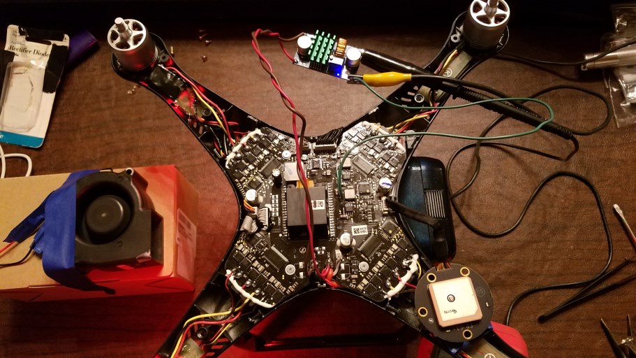
I CAN'T BELIEVE IT BUT I ACTUALLY FIXED MINE!!!! I am so happy to have my bird flying again. I was right about the 5v missing on the board. There was damage from when I stupidly plugged in one connector to the wrong port while bench testing it while out of the body. I needed to get another 5v source to feed the OFDM module and the solution was to add another 5v regulator to replace the built in one I killed. The OFDM (Lightbridge) needs a lot of power so a little 5v adapter scavenged from a car charger would not hold up. Without enough amperage the OFDM was flaking out blinking red then off then green for a second, etc. I ordered a 5v 4-5amp capable one from Amazon and when I hooked it up for a second or two I noticed that one diode was getting hot enough to start smoking a little. Sure enough, it was shorted out. I removed it which isolated the old 5V feed. Then I injected the 5v into one of the 5v leads in the black harness going to the Lightbridge module. It fired right up, I got a green light and my remote connected, I could start the motors, get telemetry, etc. I knew I was close. To make sure the circuit would hold up without overheating I went ahead and connected the camera again but as suggested in other posts I have read, I ran a fan to cool the gimbal and camera while the drone was sitting idle. I let it run for several minutes several times finally having it sit for almost 20 minutes once. Since it seemed to work just fine and run cool I hooked up the new 5v converted permanently soldering it to one side of the old bad diode area on the board that went to the 5v output. I removed the diode first of course. I put the bird back together and fly it around for about 10 minutes. I flies great, hovers, etc.
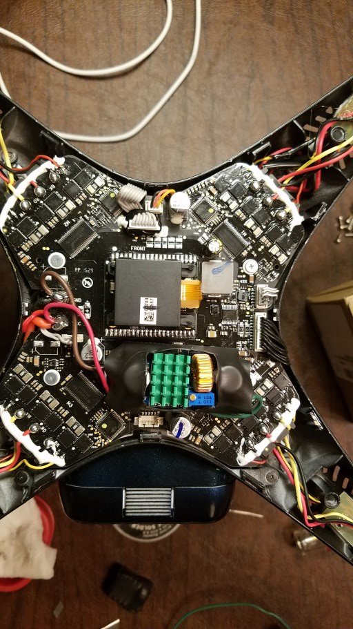
ONE PROBLEM, though. I am not sure if this is normal but my VPS gets real freaking hot. About 125 degrees if the drone is sitting for even a few minutes. So for my test flight and until I figure out what is up I have it removed for now. The drone flies fine without it but I do plan to put it or another one back on eventually. If anyone can test what sort of voltage goes to the VPS please let me know. Part of me suspects that the old 5v circuit shorted to the VPS or maybe it just got compromised when the 5v circuit was blown out. I would love some advice about that if anyone wants to chime in. Here are some photos of what I did. I hope it helps if someone else is in my shoes one day.
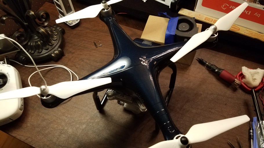
I heat shrinked the new board to keep it from rubbing on the board, then I cut a window in the heat shrink to allow some air movement over the heat sink. It fits close enough to the cover that is does not seem to move at all. Here it is reassembled with the new paint job.
This site uses cookies to help personalise content, tailor your experience and to keep you logged in if you register.
By continuing to use this site, you are consenting to our use of cookies.