DJI iOSD mini strip down to reduce weight

Joined
May 18, 2014
Messages
42
Reaction score
10
Location
Malaysia
This is an example of a DJI iOSD mini strip down to reduce weight and reduce clutter in your Phantom 2 or other DJI builds.

On many of our Phantom's we are using for stills work we are using a SonyRX100 which although is light, is quite heavy for the Ph2. So our aim is to always strip down any unnecessary weight as much as possible.

We also mount these iOSD mini's internally together with cam plug connector. This means we don't need the casing and original cabling and plug and sockets the iOSD mini comes with.

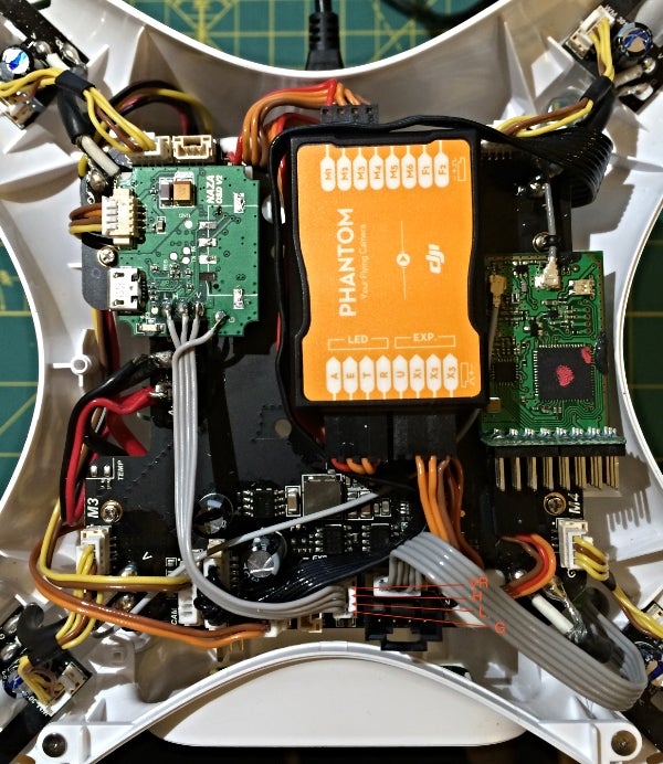
Here are some photos of the DJI iOSD mini striped down and rewired up.

This reduce it weight by around 12gr
20150518_073045.jpg

20150518_072844.jpg

20150518_072908.jpg
 
  • Like
Reactions: IflyinWY
Very cool,

Any chance of labeling the wires for those of us not in the know? :)
 
Very cool,

Any chance of labeling the wires for those of us not in the know? :)

As I understand it.
Yellow - TX or RX
Orange - RX or TX
Brown - GND /Negative
Red - VCC/Positive

I never interfered with the wires coming out of the iOSD itself other than cutting off the cable at 5cm and striping off the outer black sheath. So the 4 wires is how they were originally connected to the iOSD board itself. I then just soldered them to the cam mount board where the cam socket was removed.

After cutting it off, I plugged in the cable to the socket on the cam mount and used a multimeter to check which pins they match with which colour wire

So if you follow and match the connections as shown in the photos you cant go wrong.

Any doubts at all , check with a multimeter that you have the correct pin outs matching.
 
For the yellow and orange wires, are you not sure so you listed RX and TX?
OR
Does it not matter which goes where?
 
Like many others, I too have done basically the same thing with good results so no worries opening it up for those of you on the fence.
I strip as much non-essential weight as possible from all accessories.
 
  • Like
Reactions: jcampen
For the yellow and orange wires, are you not sure so you listed RX and TX?
OR
Does it not matter which goes where?

Yes correct, I'm really not sure which is the RX or TX but I am pretty sure that's what the orange and yellow wires are. I tried to follow the traces to see which is which, but wasn't able to find it out.

So that was the reason I posted the high res photos so that if you follow exactly how mine looks and connects up, it will work. The ones Ive done so far all work properly.

Ok, cool,

Someone smarter than us will show up with the answer, I hope.
 
I don't know how to reply to that question... :p

How you doin LuvMyTJ?
 
  • Like
Reactions: dirkclod
The four wires are CAN-H, CAN-L, VCC, GND. You don't need that clunky connector on the leg. You can splice right into the ribbon cable.

a6595835-52-photo3_zpsdf4d92c6.jpg
 
Thanks very much ianwood. :D
Now if that was a picture of a FC40 or P1, I wouldn't be dizzy and could do it to mine.
 
Ianwood,

You need to redo the solder joints at the OSD can cable and the power tap. They don't look good on this picture

Friend of yours ianwood? ROFLMAO :D
 
Good eye. Didn't see that. Those joints are indeed weak. Thankfully, not mine! I snagged the pic from RCG.
 
The four wires are CAN-H, CAN-L, VCC, GND. You don't need that clunky connector on the leg. You can splice right into the ribbon cable.

a6595835-52-photo3_zpsdf4d92c6.jpg
Good job!. I did think to do that as well, but 1.)The white silicon is very tough and I was worried about damaging any component under neath it while hacking it off. And .2) I assume the component on the can port board it has a diode, but I wasn't sure so so rather than risk that and the fiddling around to remove it and include it, I decided to include the can port board instead. But after seeing this then obviously the diode or what ever it is isn't needed?

upload_2015-5-19_7-35-59.png


I'm probably going to get an *** kicking over my soldering now to.
 
Ok done the same as well, and works fine without that component on the CAN socket board. Just a note weight wise, it removes about 2.5gr to remove the leg socket board.
 
It's a termination resistor. It's only needed when nothing is plugged in.
 
yes that's what it seems to be, after testing, its not a diode. I just did a test flight around my living room and the iOSD seems to get quite warm. I cant recall if it did this before or not.
 

Recent Posts

Members online

No members online now.

Forum statistics

Threads
143,066
Messages
1,467,357
Members
104,935
Latest member
Pauos31