Crazy Idea / Question.

50hz (20ms) refresh rate was standard with the now rare PPM (pulse position modulation). Most servos will happily work with a refresh rate between 40 and 200hz. As you probably know duty cycle and refresh rate is largely irrelevant for servo control, pulse width is what matters with most servos moving to neutral positon with a 1.5ms pulse. I was interested where the OP was reading the PWM waveform, the flight controller output is a standard servo control signal. You should see a true PWM waveform on the line that feeds the mosfet gate driver IC from the motor speed controller SOC.

I estimate, by my oscilloscope, approx. 62.5kHz frequency of pulses to the motors, each taking about 16uS
 
Like solenlife mentioned, your phantom battery could not sustain a larger amp draw for very long. I sometimes get a over current warning if I push my P4 for too long already, it get's worse when your battery is getting depleted and the voltage is dropping.
 
Hell, thinking about it more and tending to go even more mad scientist, why not get rid of the motors all together and use nitro/gas engines and use the PWM to dictate rotor pitch on a variable pitch rotor wing?
 
my idea was to use the PWM (what you call a servo signal) pulled directly off of the main board (4 per board, obviously) and have them run to completely separate ESC's.. each which has it's own feedback sensing. The power isn't really an issue because I had the thought of having one battery for the controller and possibly a dedicated battery for each ESC/motor. Maybe I'm crazy here, but to me, it seems that the controller shouldn't care what ESC it is connected to. It outputs a constant frequency signal to drive a motor controller which in turn creates a "variable" frequency (which is also the same frequency all of the time, just varying duty cycle and total "phase time" to create the same effect as different frequencies to drive the MOSFET's. The only place the frequency changes is after the MOSFET's (the effect of the VFD circuitry is a differing signal consisting of pulses of varying width to create the effect of a rising and falling differential in voltage).


No, between the flight controller and the motor controller IC. Which is a constant frequency... However, the duty cycle changes, hence PWM (Pulse Width Modulation)
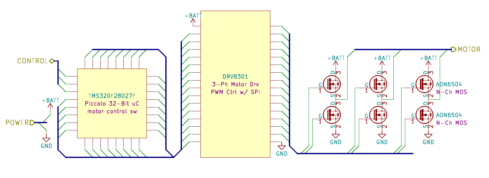
Flight Controller>---(test here)--->motor controller>---(32 bit communication)--->3 Phase driver>---(first "variable" frequency)--->MOSFET's>------>Motors
Capture.PNG


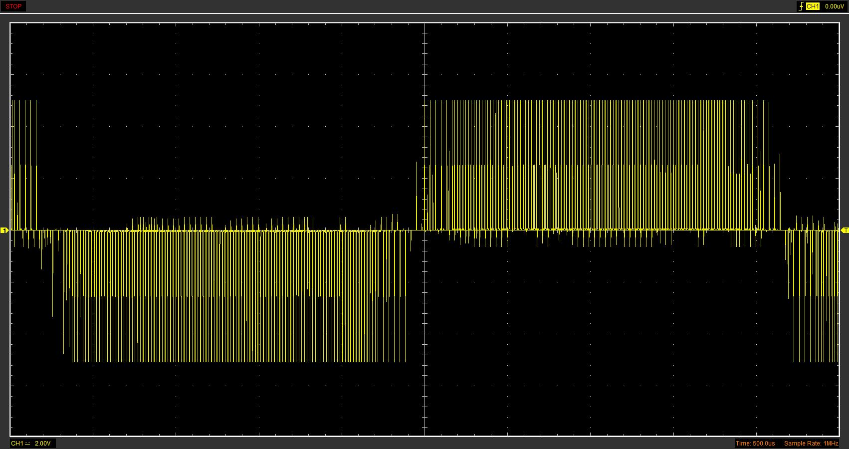
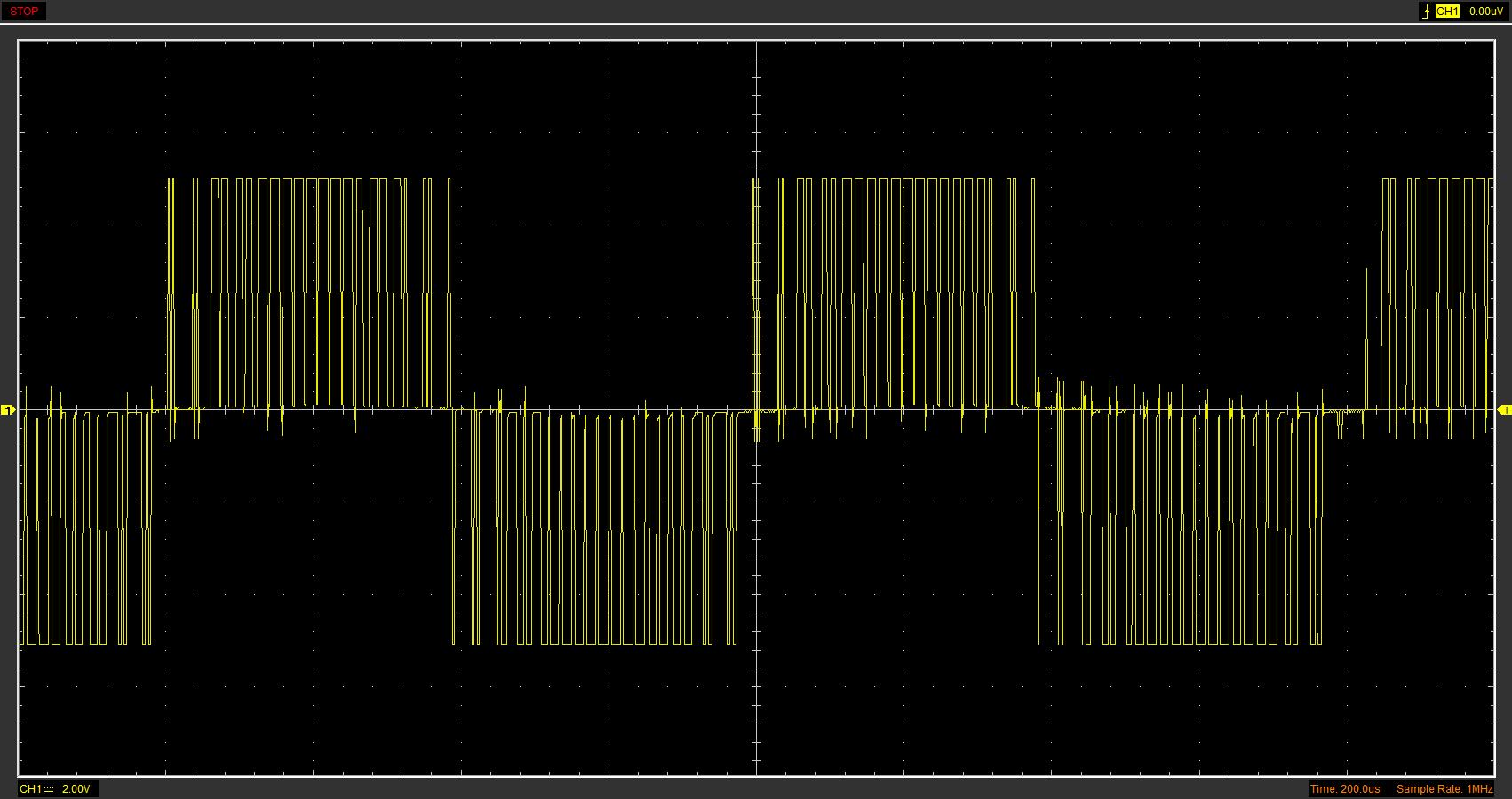
For all intents and purposes, an ESC is nothing more than a VFD. It creates a "sine wave" depending on the frequency dictated by the driver IC, through the motor controller IC, and originating at the flight controller. At low speed or throttle, there is a lot of pulses per half wave, but they have shorter duty cycles. When driving an inductive load, this has the same effect as a low frequency / low amplitude sine wave. The duty cycle always starts off low, rises up, and then falls again before each individual winding is driven the same again but in reversed polarity.
noth.jpg


Then, when at full "throttle" this all happens again but faster with longer pulses (but fewer of them since the actual pulse frequency stays the same) creating the effect of a high frequency / high amplitude sine wave thus driving the motor faster.
fullth.jpg


I believe that if we were to hijack the PWM signal before it goes into the motor controller IC and route it to standalone ESC's, it would/should work. performing a simple battery mod would allow us to supply power to these circuits. Hell, if we parallel extra batteries to the intelligent batteries of the Phantom, we could even have the intelligent battery circuitry monitor overall voltages for us through it's UART interface.
Compare what the output waveform looks like to that of a standard ESC- this Texas Instruments implementation is **** close to a pure sine wave, nothing like a Typical BLDC motor driver. I doubt a standard ESC would work with the PWM output from the controller IC. Even if did, wouldn’t upgrading the mosfets in the inverter stage be a more elegant and higher performing mod? You have the whole phantom board in the AC anyway.

Looking forward to seeing where you get with this.

I did briefly think about simply putting in bigger or more MOSFET's. I don't know now, seems to me maybe, just maybe the nitro/gas engine, variable pitch rotor idea might be pretty epic. AND if it crashes, I'm out way more money LOL. Honestly, I'm just brainstorming here and wondering if anyone else has had the urge to go mad scientist on this. From what I can see, you wont get all of the electronics to cooperate with each other for the price. However, maybe a P4 might be better for forward obstacle avoidance.
 
No, the frequency is constant and somewhat irrelevant in a PWM system. Don't confuse this with it being random though. Most common r/c stuff uses a 50hz refresh rate.

The PWM is pulse WIDTH modulation.

Don't confuse this with duty-cycle either.

Deleted
 
Hell, thinking about it more and tending to go even more mad scientist, why not get rid of the motors all together and use nitro/gas engines and use the PWM to dictate rotor pitch on a variable pitch rotor wing?

Over complicated, less reliable, noisy, messy, expensive, heavier, slower response......
No real Pro's, Just a lot of Cons
 
  • Like
Reactions: With The Birds
Are you sure DJI uses PWM .... as the most common Quad FC system is PPM ... its where Quads seriously differ from run-o-mill RC ... unless using SBus.

Nigel

Yeah, they were even nice enough to label the test points PWM1-4
 
Over complicated, less reliable, noisy, messy, expensive, heavier, slower response......
No real Pro's, Just a lot of Cons

Of course. You're right. I'll throw in the towel on this one.
 
Yeah, they were even nice enough to label the test points PWM1-4

You caught my post before I deleted ... I had the Rx and Servo pulse sections mixed up.

Nigel
 
I would not be surprised if you could get the FC to drive a different set of ESCs and bigger motors, but I doubt that is the real problem here.

The FC flight control software is going to be closely tuned to the flight response characteristics of the aircraft that it is designed for, and not just a simple feedback loop reactively applying corrections to achieve stable flight. I'm sure that it has a significant predictive element to it, in the form of at least a PID or equivalent scheme applied to all outputs. That may have some slight self-tuning capability, but I would expect that the parameters are bounded and that it would not simply adapt to a completely different aircraft.
 
Agreed. There's more going on than is obvious. If you look at FCs the software has many parameters for setting up physical/mechanical airframe characteristics for such 'tuning' as you mentioned.
As we all know those are not available to the Phantom user.
 

Recent Posts

Members online

No members online now.

Forum statistics

Threads
143,109
Messages
1,467,703
Members
104,997
Latest member
Michello