[Worklog] DIY 12v Phantom Multi-Battery Charger

Joined
Sep 1, 2015
Messages
24
Reaction score
4
Age
39
Hi All,

Thought I would share my process as I work through this incase it is of interest to anyone else, basically I am working on a 12v charging solution for my Phantom 3 batteries capable of charging 3 batteries at a time in the field and I am finding some interesting things along the way :)

Basically I have scratched the idea of using an inverter...why? Mainly because of cost and complexity, a decent 300-400w inverter runs about $300AUD then you have to factor in extra 100W chargers which are $100AUD each.

My alternative is to use DC-DC boost converters to achieve what I set out for and I have had to do some research on the stock chargers characteristics / batteries and how best to duplicate it.

The results have been interesting to say the least, basically I charged a couple of Phantom batteries and logged the voltage rise and current draw over the whole period. The stock charger is rated at 100w and only has a single combined output. Connecting the RC to the charger at the same time drops the batteries charging rate to around 75W. Running just the battery on the charger I saw a maximum of around 94W.

Peak power draw seems to occur around the 10-20min mark and current draw drops off sharply by 30minutes (batteries were around 25-30% residual charge).

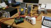
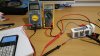
The no-load voltage for the Phantom 100W charger is 17.35V so I dialled in the DC-DC converter's no-load voltage accordingly and set the current supply to the lowest level and started charging the first battery. The Phantom batteries do not seem to incorporate any sort of charging control / current limiting and the batteries appear to take all they can get by the looks of it. I dialled up my test DC-DC power supply to 110W before chickening out and backing it down to 94W.

The theoretical maximum load for these DC-DC converters at 17.35V is 120W per unit. Originally I wanted to parallel the outputs to share the load however this won't be suitable if there is no current limiting in the batteries so I will most likely go with plan B and run 3 separate outputs to the terminal strip so each converter only has 1 battery to deal with.

I have attached the charging graph also if anyone finds it interesting and will post further updates as they come :)
 

Attachments

  • 20150927_195655.jpg
    20150927_195655.jpg
    621.2 KB · Views: 1,458
  • 20150927_151922.jpg
    20150927_151922.jpg
    542.3 KB · Views: 845
  • battercharge.jpg
    battercharge.jpg
    91.1 KB · Views: 764
  • Like
Reactions: swoopair
if there is no current limiting in the batteries so I will most likely go with plan B and run 3 separate outputs to the terminal strip so each converter only has 1 battery to deal with.

The battery packs do contain logic - if the input amperage exceeds 8amps input they will automatically disconnect.

Doesn't look or sound like this is your first go with LiPo's, so I'm sure you know the following but I given a brief description so others on the forum that might not know are now enlightened :) What we are use to with a "normal" LiPo packs with a main input and a balance lead its our charger thats the logic behind how our batteries charge with regards to time/voltage/amperages/balancing/ect..... The way the DJI Smart Packs are designed is the pack contains the logic and item they call a charger is basically just a power supply. The Smart pack contains the balancer/discharger functions.

So your on track - as I mentioned above the factory input safety cutoff amperage at the smart pack is 8amps.

On your boost converter does it provide a automatic continues voltage/amperage adjustment - regardless of input voltage? (within spec of the controller) Meaning if you have it set for 17.20V out and 4A with your input voltage at 13.8V - then lets say your input voltage drops to 12.2V does your output voltage and amperage stay at 17.20 and 4amps?

I'm sure you know this but your input amperage is going to be higher than your output amperages since your boosting 12v to 17v.

I use a iCharger 208B to charge my P3 Smart Packs - this gives me the ability to provide a lower or higher amperage to the smart pack as I choose along with being able to put a storage charge/discharge on the packs without having to rely on the smart pack. FYI you could do the same thing if you have a adjustable voltage and amperage power supply - Basically I'm using the charger in this function and not in the typical charging role.

Consider using caution when charging the packs with at a higher rate than 6amps - for a fast charge I normally only charge at 4.4amps. Most of the time I slow charge the packs overnight at a 1amp rate (FYI anything under 0.70amp and the smart pack wont recognize the input) to charge the packs this way you need to turn then on first.

Hopefully I didn't go to far off topic and provided a bit of help.
 
  • Like
Reactions: awinn17 and WetDog
Consider using caution when charging the packs with at a higher rate than 6amps - for a fast charge I normally only charge at 4.4amps. Most of the time I slow charge the packs overnight at a 1amp rate (FYI anything under 0.70amp and the smart pack wont recognize the input) to charge the packs this way you need to turn then on first.

Hopefully I didn't go to far off topic and provided a bit of help.

Thanks for the reply :) Certainly not off topic

Great to know there is a cutout point for the batteries, I was not game to keep dialling it up to find out ahaha.

As for the boost converter, I am not sure yet how it will trend with input voltage, that is the next part of my testing to measure the output voltage with an input voltage ranging from 11.5v-14v to ensure it is suitable for this task and see where the dropout voltage point is. Only cost me $20 at the end of the day :)

I will also measure the input current vs output current and figure out what its efficiency is and try to find a sweet spot where its not being stressed too much. I definitely wouldn't put more than 6A into the battery, was going to settle around the 90W mark to be honest. It is definitely pulling some current at 95W though, fuse holder gets quite hot.

The main point of this project was that I could put 1 battery on charge while another is already charging without having to disturb one that is charging etc.

I have been reading the manual until I get to testing and it should be all good (hopefully), just need to confirm the current output in relation to the input voltage:

Adjustment of V-ADJ can adjust the output voltage, clockwise adjustment increases voltage, counterclockwise adjustment decreases voltage. Whatever the input voltage is increased or decreased, the output voltage is in constant state.
 
Last edited:
That is the same booster I have. Works quite well I have mine minted to 6A. Probably have 20+ charges on it. I built mine into a case with input and output voltmeters (ammeters in the next version), 3D printed a battery connector, and use it with the DJI charging hub. Works great.
 
That is the same booster I have. Works quite well I have mine minted to 6A. Probably have 20+ charges on it. I built mine into a case with input and output voltmeters (ammeters in the next version), 3D printed a battery connector, and use it with the DJI charging hub. Works great.

Very nice :) You had any deviation of voltage / issues with yours? Main things I want to address on it when I do the final build is to solder the fuse holder to drop the resistance (gets quite hot) and possibly replace the trimpots with high precision resistors to stop them vibrating out of spec. May just glue the adjustor, we shall see.

The "current" plan is to run 3 of them to a charging bar in an enclosure with active cooling and a voltage / temperature alarm. I use FIAMM 100ah 12v batteries in the field as a power source so there is no shortage of capacity.
 
No issues with vintage changing, other than a slight drop under load. It will output the set voltage down to about 10.5 volts, so handles fluctuations well. I actually removed the fuse holder, soldered in a jumper, and use a fuse in the cig lighter end.
 
Did the 2nd round of testing today just to get a better idea of how the boost converter performs.

Dropout voltage for the converter was 10.3v with a 20ma draw at idle. Output voltage was stable right up to 17.4v where it obviously starts to increase with the input voltage.

Did a quick charge of a battery and with 91.5w going in to the battery, the boost converter is consuming 112.5w pulling a hefty 9.59amps.

Total efficiency is 81.3% will do another test after I solder the fuse holder in and use a different set of multimeter probes.
 
  • Like
Reactions: acherman
Yah, not super efficient. Part of me was hoping to be able to charge more than one battery in parallel from a cig lighter socket, but that's too much current to pull. With the DJI charging hub, this booster is great for charging one right after another.
 
Great project, thank you for sharing.

I would consider using a higher current connector with a fused suitably sized cable run direct to the car battery.

The cig lighter socket and stingy vehicle wiring rarely seem up to the task.
 
I live in South Africa, and with our pathetic excahnge rate, buying a replacement charger is out of the question.

SO i thought I would go this route, building a DC-DC converter. I have looked at the battery voltage, and it only at 11.1V , 4480mAh. It's in Phantom 3 Pro (not sure why... i thought P3 Pro 15V)

I do have a AC power adapter, that outputs 12V 5A.
Would this be OK to charge the battery. I'm thinking going up to stock 17.4V is bit too high for this battery?
 

Recent Posts

Members online

Forum statistics

Threads
143,086
Messages
1,467,528
Members
104,965
Latest member
Fimaj