- Joined
- Jan 11, 2014
- Messages
- 112
- Reaction score
- 0


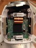
J.James said:dang I just had mine open and completely apart and all layed out on my counter the other day and could of got some pics for you.
BUT to open it you need a 1.5mm hex key.
and it seems no one seems to know any thing at all about the wiring or pin outs on the 4 pin stereo plug for the vision. other then just knowing its a plug and it plugs in to the back of the camera and does this or that. I see lots of people asking ?'s on many different boards and they have never been replied to by any one. Seems the vision out of all the models tends to be one that many know how to fly one and don't know any thing about whats under the hood. Sort of like those who drive big expensive cars and don't even know how to check the oil well alone even know what oil is or does. and if any thing goes wrong that just whip out there wallet and buy a whole new one. Sort of makes me think they were the people who didn't take apart all there toys to see what made them all tic and work when they were kids.
")
Might be something to do with the fact that DJI marketed it exactly to people who wanted to have access to aerial photography without having to get their soldering iron and multimeter out and work out connections, swap out bits, etc. It was always marketed as a "flying camera".
But hey, I started out with a mk 1 Vision and no history of much tinkering... now I've just completed building my first F450 to join it in the hangar and a P2 H3-3D materialize somewhere along the line as well
J.James said:dang I just had mine open and completely apart and all layed out on my counter the other day and could of got some pics for you.
BUT to open it you need a 1.5mm hex key.
and it seems no one seems to know any thing at all about the wiring or pin outs on the 4 pin stereo plug for the vision. other then just knowing its a plug and it plugs in to the back of the camera and does this or that. I see lots of people asking ?'s on many different boards and they have never been replied to by any one. Seems the vision out of all the models tends to be one that many know how to fly one and don't know any thing about whats under the hood. Sort of like those who drive big expensive cars and don't even know how to check the oil well alone even know what oil is or does. and if any thing goes wrong that just whip out there wallet and buy a whole new one. Sort of makes me think they were the people who didn't take apart all there toys to see what made them all tic and work when they were kids.
The folks over at MotorPixie have a diagram that show the pin out for the 4 pin stereo plug.
https://docs.google.com/viewer?a=v&pid= ... EwNDE4ZDk0
To be fair here is the link to MotorPixie's home page.
https://sites.google.com/site/motorpixiegimbals/home
Not sure if this thread is still running - having an issue with my sat and batt readings.
Do the wires that link the fc200 cam to the unit also transmit said details via wifi?