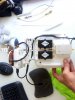
ive already done FPVLR stage 2 mods to transmitter...both to the extender and to transmitter. i can add my own antennas to each of the 3 antenna mounts now.
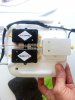
question: i now have the amps for all 3 antennas (two 2.4ghz @2.5 amps + 1 5.8ghz@1 amp)...are these amps SHIELDED?
ie, what if i want to mount them all into a central "velcro tower of amps" on the rear side of transmitter and all stacked very close to each other...offset by a small distance to balance CG? would the radiation defeat my purposes?
")