DJI Upgrade Board has CAN bus?

Joined
Jul 27, 2014
Messages
15
Reaction score
0
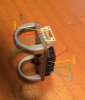
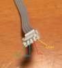
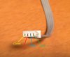
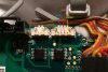
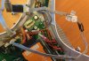
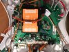
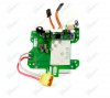
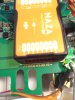
I have an FC40 and I just bought and installed the DJI upgrade board, P330-CB-H3-2D V3, since I'm planning on adding a gimbal in the future. I noticed that my upgrade board has a 4-pin port on it, is this a CAN bus?While other pictures I had seen online do not have it,. It looks like I have the V3 version of the board,All the pictures I saw online are of the V1 board. Is this a CAN port on the V3 board? If I buy this:http://www.ebay.com/itm/221440725224?_trksid=p2059210.m2749.l2649&ssPageName=STRK:MEBIDX:IT, will I be able to just attach it and I will have a CAN port on my FC40?
 

Attachments

  • photo 2.JPG
    photo 2.JPG
    288.6 KB · Views: 3,000
  • imagemagic.php.jpg
    imagemagic.php.jpg
    256.6 KB · Views: 2,207
  • photo 1.JPG
    photo 1.JPG
    284.4 KB · Views: 2,022
Wow...it very well may be the canbus port for the leg extension like on the P2 board! I've never seen an upgrade board with that on it (mine certainly doesn't have it), so they may have added it for v3.0 of the part! It looks like the traces from that port go to the same controller chip that's connected to the CL/CH pads we normally solder a canbus lead to.

My bet is that plugging in that cable from the leg port you linked (on ebay) will get you an active canbus port, I'd say go ahead and try it!
 
You are correct, the chip those PCB traces go to is a Texas Instruments HV232Q, a CAN transceiver. My only concern was that I have a DJI CAN cable (I think it is at least) that I tried to plug in, but the socket on the PCB does not quite match, it's close but it doesn't fit.

Anyway, I've already ordered the landing gear with the CAN port attached, so I'll try that when I get it and post an update.
 
I received the CAN bus module that comes attached to the landing gear leg last night. I was able to quickly check if the CAN bus cable from it fits in the 4 pin port on the Upgrade Board, which it does not.

The 4 pin connector on the Upgrade Board looks like it would mate with the cable that goes to the compass module (if it was 4 pin instead of 5). I will post pictures when I get a chance.
 
I finally had time to purchase a BTU module and connect it.....and it works!!! It's definitely a CAN bus connector (just not the typical DJI type). I will post a more detailed update when I have more time.
 
nudeymagazineday said:
I finally had time to purchase a BTU module and connect it.....and it works!!! It's definitely a CAN bus connector (just not the typical DJI type). I will post a more detailed update when I have more time.

Yes please, even if you could just confirm the pinouts on the port :)

How did you connect the BTU?
 
Sorry for the long delay, I've been away on business for awhile. To interface to the 4-pin CAN bus connector on the upgrade board, I cut two different ribbon cables in half and spliced it back together with 2 different ends on it, 1 with the standard 4-pin DJI CAN bus connector and the other to the 4-pin connector on the main board. The hardest part was finding the 4-pin connector that goes to the main board, I ended up getting a 5-pin cable for a compass module and cutting the extra pin off to make it fit. I also bought a a Phantom 2 CAN module, shown here: http://www.atlantahobby.com/Store/pc/viewPrd.asp?idproduct=18121. Below are the pin outs for each end of the cable/connector:
 

Attachments

  • IMG_2396.JPG
    IMG_2396.JPG
    258.1 KB · Views: 2,590
  • IMG_2399.JPG
    IMG_2399.JPG
    177.4 KB · Views: 2,450
  • IMG_2400.JPG
    IMG_2400.JPG
    174.5 KB · Views: 2,307
  • IMG_2397.JPG
    IMG_2397.JPG
    574 KB · Views: 1,842
  • IMG_2402.JPG
    IMG_2402.JPG
    940.1 KB · Views: 2,374
Excellent!! Thanks for the pinout diagrams, exactly what I needed :)

That's so weird that they would finally add a canbus header to the P1 upgrade board but use a connector that doesn't even match the scheme used with the P2's port. I'll see if I can find any that fit.

How did you determine the pinouts on the new port on the board? Just guessed it would be the same as the P2 port?
 
No problem OI, glad I could help. I don't understand either why they wouldn't use the same connector, it's pretty annoying.

To figure it out I worked my way backwards from the CAN Bus module that comes attached to the landing gear. Since the pin out for the black, 4-pin connector is well known, I was able to find the pinout for that easily. I had already cut a CAN Bus cable in half and stripped the ends, so I could check the continuity from each known pin on the black connector, to each wire on the white connector. Once I had that, I could tell which pin was which on the upgrade board side.

Interestingly, on the CAN Bus leg module, between the black and white connectors, on the +6V line, there is a ~236ohm resistor. All of the other pins are just dead shorts.

Do you know what the manufacturer or part # for the connectors the connectors these cables use? I was trying to find a source so I could crimp my own cables, I didn't want to splice 2 cables together but I couldn't figure out where to buy the crimp pins and pin housings from.
 
nudeymagazineday said:
No problem OI, glad I could help. I don't understand either why they wouldn't use the same connector, it's pretty annoying.

To figure it out I worked my way backwards from the CAN Bus module that comes attached to the landing gear. Since the pin out for the black, 4-pin connector is well known, I was able to find the pinout for that easily. I had already cut a CAN Bus cable in half and stripped the ends, so I could check the continuity from each known pin on the black connector, to each wire on the white connector. Once I had that, I could tell which pin was which on the upgrade board side.

Interestingly, on the CAN Bus leg module, between the black and white connectors, on the +6V line, there is a ~236ohm resistor. All of the other pins are just dead shorts.

Do you know what the manufacturer or part # for the connectors the connectors these cables use? I was trying to find a source so I could crimp my own cables, I didn't want to splice 2 cables together but I couldn't figure out where to buy the crimp pins and pin housings from.

Has anyone come up with a place to get the 4 pin female connector that will connect into the DJI Upgrade Board V3.0 Can Bus board yet??
 
  • Like
Reactions: rmhome
I am getting ready to install the data link for ground station, when I set up my fpv i pulled the can bus connector cable up the leg and and reconnected it inside the Phantom 2, I also have my iOSD inside my phantom. Now I would like to set the air end of the data link on the outside but alas, the black can bus cable end wont fit through the hole to plug it in inside to my iOSD. Can anyone tell me what goes on inside that black can bus cable? is it just 4 wires? Can I cut the cable, run it through the hole and solder the individual wire back together again on the inside?
 
The black CAN bus cable is a shielded cable, so it's best not to cut it if you can avoid it, but it's just 4 colored wires and the shield, similar to a USB cable. It can be cut and spliced back together with no real ill effects, just remember to make sure the shield is also restored.


For anyone still looking, the 4 pin connector for the Central board is a Molex PicoBlade 51021 series.

DigiKey part numbers for the..

Housing - http://www.digikey.com/product-detail/e ... -ND/242844

Pins, 26-28awg wire - http://www.digikey.com/product-detail/e ... -ND/467835

Pins, 28-32awg wire - http://www.digikey.com/product-detail/e ... -ND/242897

It takes either an expensive crimper ($300+) to put the pins on correctly, or you can get one for around $50 that does the job good enough after some practice.
 

Members online

Forum statistics

Threads
143,087
Messages
1,467,528
Members
104,965
Latest member
cokersean20